Fish pond feeding device

A technology for fish ponds and equipment, applied in fish farming, application, climate change adaptation, etc., can solve problems such as motor burnout, fish electrocution death, user economic loss, etc., and achieve the effect of avoiding feed blockage

Inactive Publication Date: 2019-01-08
麻景峰
View PDF1 Cites 2 Cited by
  • Summary
  • Abstract
  • Description
  • Claims
  • Application Information

AI Technical Summary

Problems solved by technology

[0003] When the above-mentioned patent is used, the motor driving the throwing tray is located directly below the throwing tray and directly above the fish pond. When the floating mechanism rolls over due to strong wind

Method used


Image

  • Fish pond feeding device
  • Fish pond feeding device
  • Fish pond feeding device

Examples


Embodiment 1

[0076] according to Figure 1 to Figure 20 As shown, a fish pond bait casting device described in this embodiment includes a material storage component located in a feed warehouse adjacent to the fish pond, and a material throwing component floating on the water surface of the fish pond.

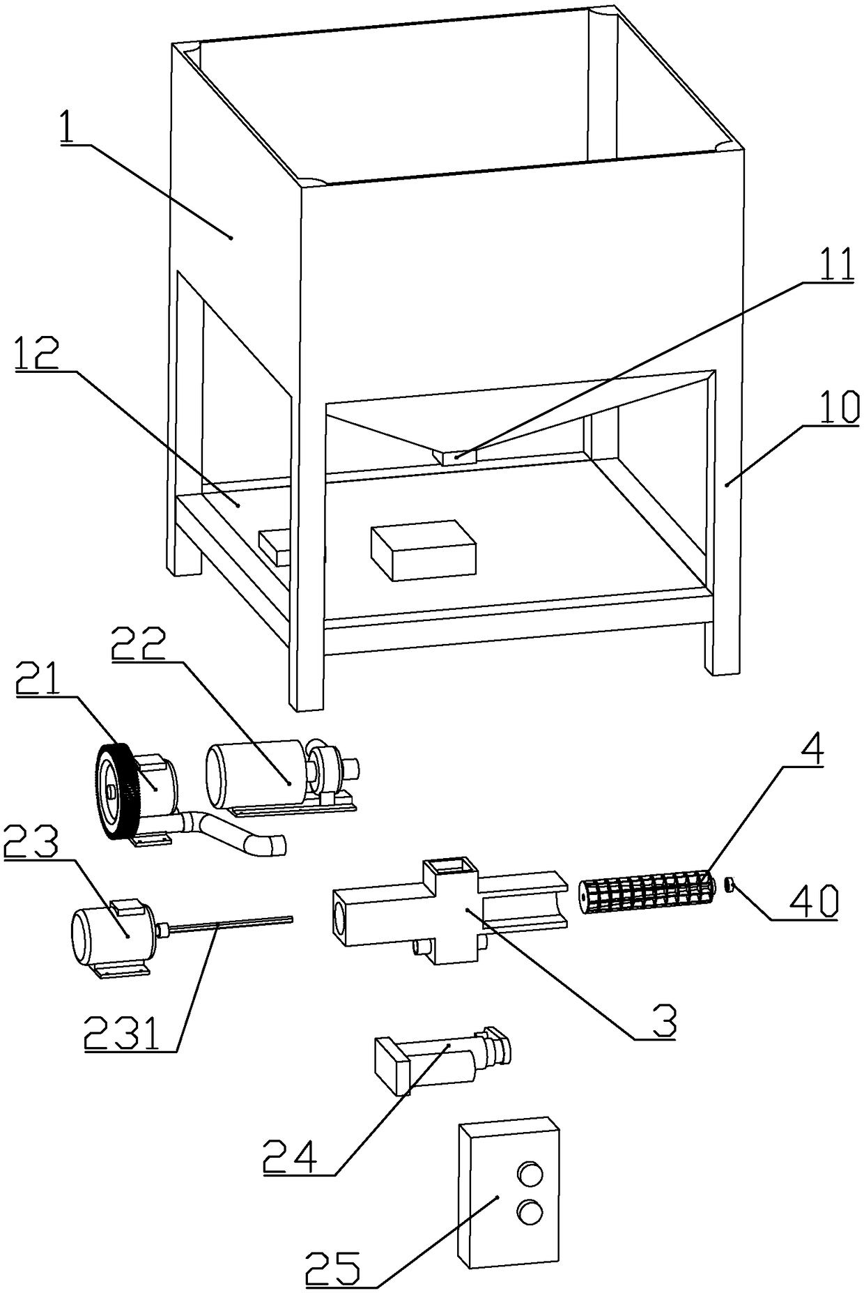
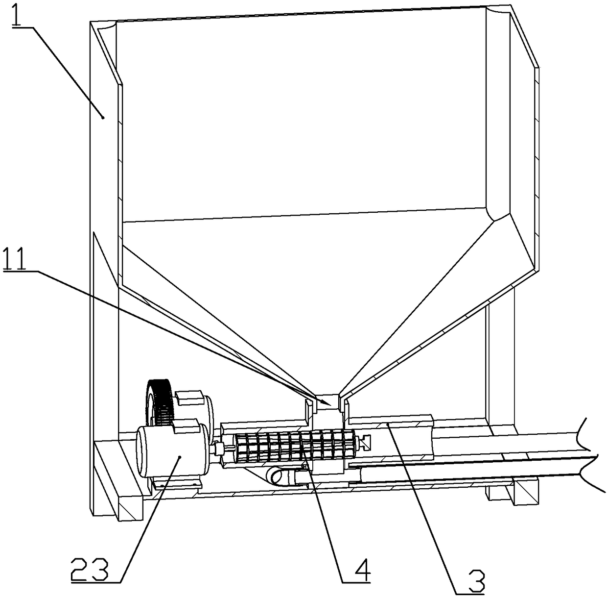
[0077] The material storage assembly includes a bracket 10 and a material tank 1 fixedly installed on the bracket, and a discharge pipe 11 is formed in the center of the bottom of the material tank.

[0078] The material throwing assembly includes a floating support 5 above the water surface, a plurality of floats connected to the floating support through connecting rods, a lower bottom plate 52 fixedly connected to the lower end of the floating support, and a rotatable bottom plate 52 connected above the floating support. It is used for throwing feed into the throwing tray in the fish pond; each float is arranged on the outside of the floating support at equal angles, so that the throwing c...

Embodiment 2

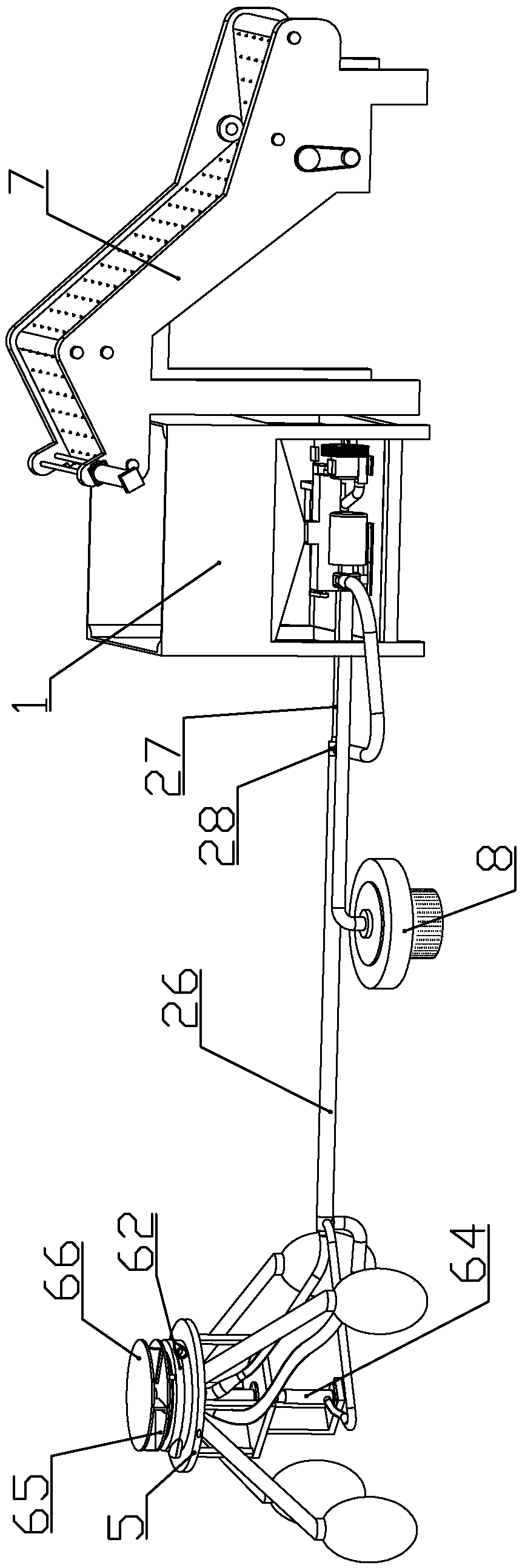
[0129] combine Figure 21 to Figure 23 As shown, this embodiment makes the following improvements on the basis of Embodiment 1: it also includes a material transport assembly 7 located on one side of the storage assembly; the material transport assembly includes a conveyor belt seat 71, and is installed on the conveyor belt The conveyor belt 72 on the seat; the outer wall of the conveyor belt is evenly fixed with spikes 720, so that after a bag of feed is placed on the conveyor belt, the spikes enter the bag, so that the feed will not slip during transportation. The outer wall of the conveyor belt has no spikes near the two sides.

[0130] The conveyor belt is in turn a placing part 721 close to the bottom surface and arranged horizontally, a feeding part 722 arranged obliquely and extending to the top of the chute, and a feeding part 723 arranged obliquely into the chute;

[0131] The two ends of the inner wall of the conveyor belt on the conveyor belt seat are respectively ...


PUM


Abstract

The invention discloses a fish pond feeding device. The device comprises a material storage assembly and a material throwing assembly. The material storage assembly comprises a bracket and a trough. The material throwing assembly comprises a floating bracket, floaters, a lower bottom plate and a material throwing tray for throwing a feed into the fish pond. A bottom plate is fixedly connected to afirst blower for blowing feed falling from a discharge pipe into the material throwing disc. An upper end of the floating bracket is rotatingly connected to a hydrodynamic rotating wheel that is under the material throwing disc and drives the material throwing disc to rotate. A bottom plate is fixedly connected to a water pump which can drives the hydrodynamic rotating wheel to rotate. A materialdividing cone which can be inserted into a feeding pipe is formed at the center of the material throwing disc. The lower end of the lower bottom plate is equipped with a hydrodynamic pushing rod which is driven by water flow generated by the water pump to drive the material throwing disc to move axially. According to the fish pond feeding device, by setting a motor, the first blower and the waterpump on the bottom plate, electric components are not used in the material throwing assembly, and the damage to fishes and the economic losses of a user caused by electric leakage when the material throwing assembly is turned over and the electric components are immersed in the fish pond are avoided.

Description

technical field [0001] The invention belongs to the technical field of fishing gear, and in particular relates to a fishing pond baiting device. Background technique [0002] Document number is that the Chinese patent document of CN203985566U discloses a kind of fishpond automatic feeding device, comprises floating mechanism, throwing material dish, feed pipe, material storage box, blowing mechanism and feeding mechanism, and described throwing material dish is rotatably arranged on On the floating mechanism, one end of the feeding pipe is connected with the throwing tray, the storage box is provided with a feeding port, the blowing mechanism is arranged at the other end of the feeding pipe, and the feeding mechanism includes a feeding cylinder, a feeding Screw and screw driver, the feeding screw is arranged in the feeding barrel, the screw driver is used to drive the feeding screw to rotate, the upper side of the feeding barrel communicates with the feeding port of the stor...

Claims


Application Information

Patent Timeline
IPC IPC(8): A01K61/80
CPCA01K61/80Y02A40/81
Inventor 麻景峰
Owner 麻景峰
Why Eureka
Try Eureka