
Waste gas absorption and purification equipment

A technology for purifying equipment and waste gas, applied in chemical instruments and methods, dispersed particle separation, combined devices, etc., can solve problems such as difficulty in eliminating exhaust gas, low efficiency and effect of liquid separation, and difficulty in removing fine droplets, etc. The effect of improving absorption efficiency, increasing gas-liquid contact area, and strong trapping ability

Inactive Publication Date: 2019-01-08
霸州市辉月网络技术有限公司
View PDF2 Cites 2 Cited by
  • Summary
  • Abstract
  • Description
  • Claims
  • Application Information

AI Technical Summary

Problems solved by technology

Although some exhaust gas absorption and purification equipment are equipped with wire mesh demisters at the gas outlet, the processing capacity of the wire mesh internals is usually more than 15 microns, and the efficiency and effect of liquid separation are low, making it more difficult to remove gases On the other hand, the liquid separated by the wire mesh demister and accumulated inside the wire mesh is easy to form back-mixing with the discharged air flow and be taken out during the falling process, and it is difficult to eliminate the liquid in the discharged gas. liquid condition

Method used


Image

  • Waste gas absorption and purification equipment
  • Waste gas absorption and purification equipment
  • Waste gas absorption and purification equipment

Examples


Embodiment 1

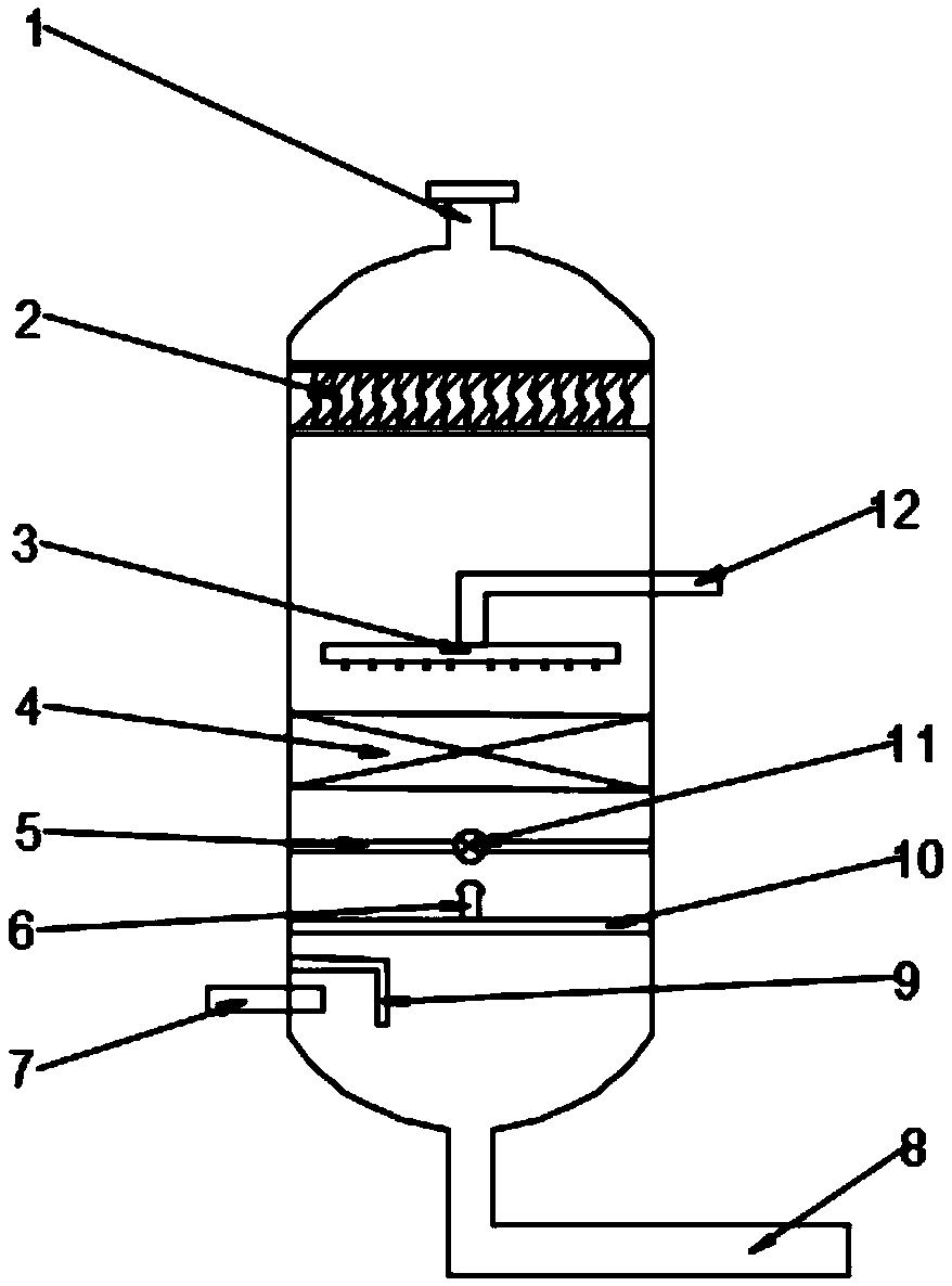
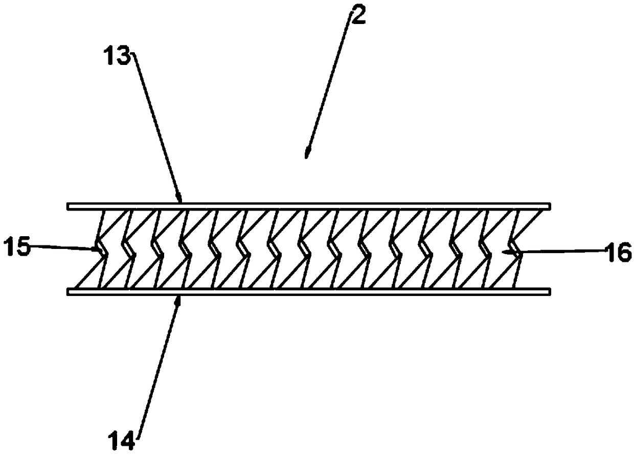
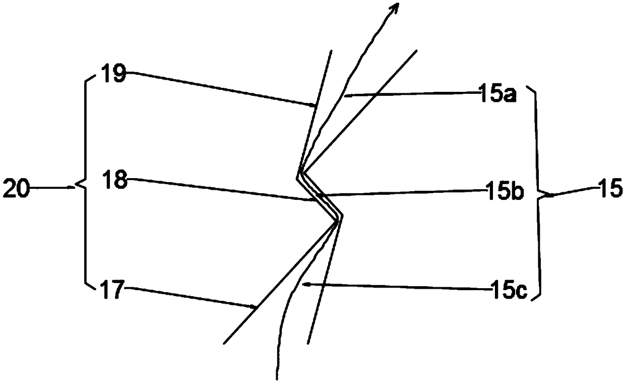
[0023] see Figure 1-4 , a waste gas absorption and purification equipment, comprising a gas outlet 1, a gas inlet 7, a liquid outlet 8 and a liquid inlet 12, the liquid inlet 12 is connected to a liquid distributor 3, and a gas-liquid separation device 2 is arranged above the liquid distributor 3, The gas-liquid separation device 2 is located on the upper part of the absorption tower, between the gas outlet 1 and the liquid inlet 12; the gas-liquid separation device 2 includes a first support 13 and a second support 14, the first support 13 and the second support A first baffle 17, a second baffle 18 and a third baffle 19 are arranged between the supports 14; the first baffle 17, the second baffle 18 and the third baffle 19 form a The baffles 20, the gas-liquid separation device 2 includes a plurality of baffles 20 arranged in parallel, and the first flow channels 15 and the second flow channels 16 arranged in a staggered manner are formed between adjacent baffles 20; After ...

Embodiment 2

[0029] Compared with Example 1, a gas-liquid separation plate 9 is arranged above the gas inlet 7 corresponding to the gas inlet 7, as figure 1 As shown, the gas-liquid separation plate 9 is located below the second separator 10, and the gas-liquid separation plate 9 can separate the gas passed through for the first time from gas to liquid.


PUM


Abstract

The invention relates to the technical field of purification machinery equipment, in particular to waste gas absorption and purification equipment and solves the problem that liquid is carried in exhaust gas. The invention has the technical key points that the waste gas absorption and purification equipment comprises a gas outlet, a gas inlet, a liquid outlet and a liquid inlet; the liquid inlet is connected with a liquid distributor, and a gas-liquid separation device is arranged above the liquid distributor and is positioned between the gas outlet and the liquid inlet; the gas-liquid separation device comprises a first supporting piece and a second supporting piece, and first baffles, second baffles and third baffles are arranged between the first supporting piece and the second supporting piece; one first baffle, one second baffle and one third baffle form a baffle; the gas-liquid separation device comprises a plurality of baffles arranged in parallel, and a first overflow passage and a second overflow passage which are arranged in a staggered manner are formed between the adjacent baffles. As the waste gas absorption and purification equipment is provided with the gas-liquid separation device, the gas-liquid separation device can more thoroughly separate the gas from the liquid carried in the gas.

Description

technical field [0001] The invention relates to the technical field of purification machinery and equipment, in particular to waste gas absorption and purification equipment. Background technique [0002] Exhaust gas purification mainly refers to the work of treating industrial waste gas such as dust particles, flue gas smoke, odorous gas, and toxic and harmful gases generated in industrial places. Common waste gas purification includes factory smoke and dust waste gas purification, workshop dust waste gas purification, organic waste gas purification, waste gas odor purification, acid-base waste gas purification, chemical waste gas purification, etc. [0003] Most of the existing waste gas absorption and purification equipment is equipped with a spray device, and the waste gas absorbent is sprayed out through the spray device, and the sprayed absorbent contacts with the gas to be purified to achieve the purpose of purification or absorption. Although some exhaust gas absorp...

Claims


Application Information

Patent Timeline
IPC IPC(8): B01D53/18B01D50/00
CPCB01D53/18B01D53/185B01D50/40
Inventor 宗磊
Owner 霸州市辉月网络技术有限公司
Learn More