Visual identification device for type of integrated circuit punching system and identification method and application

An integrated circuit and visual recognition technology, applied in sorting and other directions, can solve problems such as inability to detect product varieties

Inactive Publication Date: 2019-01-08
TONGLING SANJIA YAMADA TECH
View PDF5 Cites 3 Cited by
  • Summary
  • Abstract
  • Description
  • Claims
  • Application Information

AI Technical Summary

Problems solved by technology

This patent is from the perspective of mold screening to judge whether the mold matches the product type, but it cannot detect whether the product type is correct

Method used


Image

  • Visual identification device for type of integrated circuit punching system and identification method and application

Examples


Embodiment 1

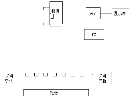
[0016] Embodiment 1: The visual recognition device of the kind of integrated circuit die-cutting system, it comprises feeding guide rail, is distributed with visual imaging system on the vertical direction between described feeding guide rail, described visual imaging system is connected with PC signal by PLC, PC and PC The display screen signal is connected, and the PLC is also signal-connected with a manipulator; the visual imaging system includes a light source positioned at the bottom of the feed guide rail and a camera above the feed guide rail, and the camera is connected with the PLC signal; the feed guide rail includes a horizontal interval distribution The left feeding guide rail and the right feeding guide rail are driven by a motor to move synchronously.

Embodiment 2

[0017] Embodiment 2: The difference from Embodiment 1 is that the left feeding guide rail and the right feeding guide rail are driven by a cylinder to move synchronously.

Embodiment 3

[0018] Embodiment 3: The difference from Embodiment 1 is that the left feeding guide rail and the right feeding guide rail are hydraulically driven to move synchronously.

[0019] The identification method of the visual identification device of the variety of integrated circuit punching system, which includes the following steps: (1) Judgment of abnormal position: the manipulator puts the correct lead frame on the feeding guide rail, and the visual imaging system detects the placement of the lead frame And feed back to PLC, PLC drives visual imaging system to take pictures, PC selects a search range of heterotopic hole, gives a positioning range to determine the position parameters of the heterotopic hole, saves the parameters to PLC after debugging to become template of heterotopic hole, manipulator Grab a new lead frame and put it on the feeding guide rail to compare the different position holes. If the similarity with the different position hole template is greater than or e...


PUM


Abstract

The invention discloses a visual identification device for types of integrated circuit punching systems and an identification method and application. The visual identification device comprises conveying guide tracks, wherein a visual imaging system is distributed in a vertical direction between the conveying guide tracks; the visual imaging system is in signal connection with a display screen through a PLC (Programmable Logic Controller); the PLC is in signal connection with a manipulator. The visual identification device has the beneficial effects that through linkage of the visual imaging system and the PLC, displacement holes, lead frame sizes and pin numbers of lead frame products on the conveying guide tracks are detected, when the three parameters meet requirements, the result showsthat a lead frame is a type meeting requirements, the lead frame is fed to a next operation station by using the conveying guide tracks, if one parameter does not meet the requirements, the result shows that the lead frame is not a type meeting the requirements or the product self has defects, then the lead frame is placed into an unqualified product box, visual detection on varieties and appearances of lead frames is achieved, and lead frames of different types can be classified according to the method, thus being convenient and rapid.

Description

technical field [0001] The invention relates to the field of punching and forming of integrated circuits, in particular to a visual recognition device and a recognition method for varieties of integrated circuit punching systems. Background technique [0002] Due to the rapid development of information technology, the semiconductor industry is also developing rapidly, so the requirements for automation equipment are getting higher and higher. In the integrated circuit punching and forming equipment, the mold is the main tool to complete the punching and forming of the product. At the same time, there are corresponding molds for different product varieties. If the product that does not match the mold model is put into the mold Punching will lead to substandard products or even damage the mold. In order to avoid this situation, it is necessary to ensure that the correct product is put into the corresponding mold. In the past, the type identification of the lead frame was main...

Claims


Application Information

Patent Timeline
Patent Type & Authority Applications(China)
IPC IPC(8): B07C5/02B07C5/342B07C5/36
CPCB07C5/02B07C5/3422B07C5/362B07C2301/0008B07C2501/0063
Inventor 李建王俊徐紫奎刘正龙
Owner TONGLING SANJIA YAMADA TECH
Why Eureka
Try Eureka