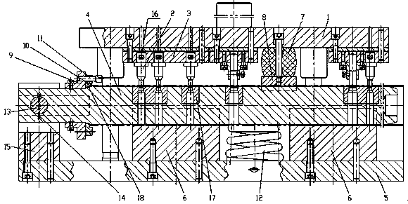
Stamping die with irregular holes distributed in axial direction of round pipe
An axially distributed, stamping die technology, applied in the field of stamping die, can solve the problems of high labor and mold cost, rough processing method, impact on production efficiency, etc., to save labor and mold cost, solve reliability and uniqueness, The effect of ensuring the angular dimension accuracy
- Summary
- Abstract
- Description
- Claims
- Application Information
AI Technical Summary
Problems solved by technology
Method used
Image
Examples
Embodiment 1
[0026] Example 1, such as figure 1 , Figure 5 , Figure 6 , Figure 7 and Figure 8 Shown in, the present invention is an upper template 1, a circular punch 2, a punch fixing plate 3 and an elastic unloading device; the circular punch 2 is fixedly installed on the upper template 1 through the punch fixing plate 3; the lower The mold structure includes a lower mold 4, a lower template 5, a support seat 6 and an index positioning device; the lower mold 4 is supported and installed on the lower template 5 through the support seat 6; Indexing and positioning device; an elastic unloading device is arranged between the upper template 1 and the lower mold 4, and the elastic unloading device resets the circular punch 2 after stamping; the circular punch 2 is detachable in multiple groups, The number of groups is the same as the number of holes distributed in the axial direction of the processed round pipe; the circular punch 2 is based on the indexing positioning device, corresp...
Embodiment approach
[0028] a. If figure 2 , image 3 and Figure 4 As shown in , a schematic diagram of the distribution structure of each hole on the processed round tube, when punching the first hole position 19, first open the process slot 25 on the left end face of the processed round tube, and set it according to the external size of the processed round tube The size of the process slot 25, this process slot 25 can be snapped into the positioning turntable 10, with the positioning turntable 10 as the lengthwise reference and the distribution reference of the angle on the circumference of each punching hole. First pull out the threading pin 7, and rotate the positioning turntable 10 clockwise, so that the positioning slot on the positioning turntable 10 is aligned with the angular indexing position of the first hole 19 marked on the indexing plate 9, and after alignment, use the threading Insert the pin 7 into the positioning turntable 10 for locking; lift the lower mold 4 lightly by hand, ...
Embodiment 2
[0033] Embodiment 2, on the basis of embodiment 1, lower mold structure is carried out optimized design, as figure 1 and Figure 8 As shown in , a support spring 12 is provided between the lower mold 4 and the lower template 5; the left end of the lower mold 4 is hingedly mounted on a hinge support 15 through a mandrel 13 and a cotter pin 14 .
[0034] Take the stamping first hole position 19 as an example, and the rest of the processing holes are the same. When punching the first hole 19: pull out the threading pin 11 first, and rotate the indexing plate 9 clockwise to make the positioning slot on the positioning turntable 10 and the angle indexing position of the first hole 19 marked on the indexing plate 9 Alignment, after alignment, insert the pin 7 into the positioning turntable 10 to lock; lift the lower die 4 slightly by hand, insert the round tube into the lower die 4, push the round tube and snap the process slot 25 on the round tube Insert the positioning pin 18 s...
PUM
 Abstract
Description
Claims
Application Information
 - R&D
- Intellectual Property
- Life Sciences
- Materials
- Tech Scout
- Unparalleled Data Quality
- Higher Quality Content
- 60% Fewer Hallucinations
Browse by: Latest US Patents, China's latest patents, Technical Efficacy Thesaurus, Application Domain, Technology Topic, Popular Technical Reports.
© 2025 PatSnap. All rights reserved.Legal|Privacy policy|Modern Slavery Act Transparency Statement|Sitemap|About US| Contact US: help@patsnap.com


