Cutting, drilling and grinding mechanism

A drilling, grinding and belt pulley technology, applied in the field of mechanical processing, can solve the problems of high cost, low degree of automation of small equipment, inability to quickly adjust the position of the working platform, etc., and achieve the effect of convenient operation and simple structure

Inactive Publication Date: 2019-01-08
金华市新鑫机电设备有限公司
View PDF0 Cites 5 Cited by
  • Summary
  • Abstract
  • Description
  • Claims
  • Application Information

AI Technical Summary

Problems solved by technology

[0002] At present, the cutting machine and the drilling and milling machine on the market are independent mechanical equipment. When people process parts, they need to buy these two kinds of equipment. The large-scale processing equipment on the market is expensive, while the small-scale equipment has a low degree of automation and cannot quickly adjust the position of the working platform. Therefore, there is an urgent need for a safe, efficient cutting, drilling and grinding mechanism with multiple processing functions.

Method used


Image

  • Cutting, drilling and grinding mechanism
  • Cutting, drilling and grinding mechanism
  • Cutting, drilling and grinding mechanism

Examples


Embodiment Construction

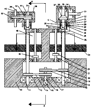
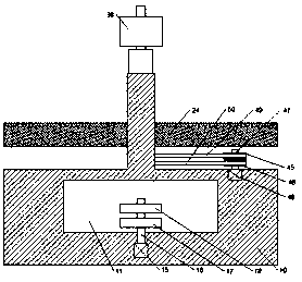
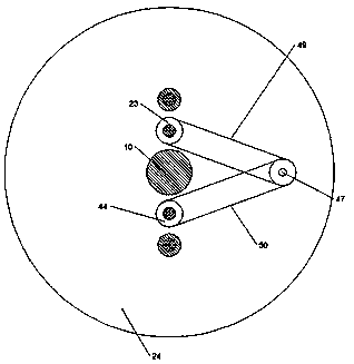
[0012] Combine below Figure 1-4 The present invention will be described in detail.

[0013] refer to Figure 1-4 A cutting, drilling and grinding mechanism according to an embodiment of the present invention includes a cutting main body 10, a transmission chamber 11 is provided inside the cutting main body 10, and the bottom wall of the transmission chamber 11 is symmetrically rotated left and right and extends upwards through the The transmission shaft 12 on the top end surface of the cutting main body 10, the cross groove interface 25 is fixedly installed on the top end surface of the left and right transmission shafts 12, the first pulley 13 is fixedly installed on the left shaft of the left and right transmission shafts 12, the cutting main body A first motor 15 is fixedly installed on the bottom end surface of 10, and a power shaft 16 is fixedly installed on the top end surface of the upward output shaft of the first motor 15, and a second pulley 17 is fixedly installed...


PUM


Abstract

The invention discloses a cutting, drilling and grinding mechanism. The cutting, drilling and grinding mechanism comprises a cutting main body, wherein a transmission cavity is arranged inside the cutting main body; transmission shafts which upwards extend to penetrate through the top end surface of the cutting main body are symmetrically and rotatably mounted in the bottom wall of the transmission cavity left and right; cross-shaped groove interfaces are fixedly mounted on the top end surface of the left and right transmission shafts; a first belt wheel is fixedly mounted on the left one of the left and right transmission shafts; a first motor is fixedly mounted on the bottom end surface of the cutting main body; the top end surface of the upward output shaft of the first motor is fixedlyequipped with a power shaft; a second belt wheel is fixedly mounted on the power shaft; the position, on the power shaft, of the upper side of the top end surface of the second belt wheel is fixedlyequipped with a third belt wheel; a fourth belt wheel is fixedly mounted on the transmission shaft; a first transmission belt is rotatably mounted between the first belt wheel and the second belt wheel in a matched mode; and a second transmission belt is rotatably mounted between the fourth belt wheel and the third belt wheel in the matched mode.

Description

technical field [0001] The invention relates to the field of mechanical processing, in particular to a cutting, drilling and grinding mechanism. Background technique [0002] At present, the cutting machine and the drilling and milling machine on the market are independent mechanical equipment. When people process parts, they need to buy these two kinds of equipment. The large-scale processing equipment on the market is expensive, while the small-scale equipment has a low degree of automation and cannot quickly adjust the position of the working platform. Therefore, a safe, efficient cutting, drilling and grinding mechanism with multiple processing functions is urgently needed. Contents of the invention [0003] The object of the present invention is to provide a practical cutting, drilling and grinding mechanism for overcoming the above-mentioned defects in the prior art. [0004] A cutting, drilling and grinding mechanism according to an embodiment of the present invent...

Claims


Application Information

Patent Timeline
Patent Type & Authority Applications(China)
IPC IPC(8): B23P23/04
CPCB23P23/04
Inventor 林甲菁
Owner 金华市新鑫机电设备有限公司
Why Eureka
Try Eureka