Construction waste treatment device for civil engineering

A construction waste and processing device technology, applied in the direction of manufacturing tools, auxiliary molding equipment, ceramic molding machines, etc., can solve the problems of less shaking, heavy quality, and large suction, and achieve increased stability, improved quality, and improved adhesion force effect

Inactive Publication Date: 2019-01-08
GUIZHOU UNIV
View PDF7 Cites 2 Cited by
  • Summary
  • Abstract
  • Description
  • Claims
  • Application Information

AI Technical Summary

Problems solved by technology

[0004] The object of the present invention is to provide a construction waste processing device for civil engineering, to solve the problem that the concrete waste processing die-casting device proposed in the above background technology is not only complex in structure, but also has a single function. During the die-casting process of concrete waste, a large amount of Smoke and dust, but because the concrete waste die-casting device itself lacks a dust removal mechanism, the operator will inhale a large amount of dust when operating the concrete die-casting device, which will cause serious damage to the operator's respiratory tract and lungs, making the operator's health unable to be guaranteed. ; Due to the large volume and heavy weight of the concrete waste die-casting device, in order to facilitate the movement of the concrete waste die-casting device, movable rollers will be installed at the bottom, but due to the structure of the roller itself, it cannot meet the needs of the concrete waste die-casting device. The stability required for normal work, so that the concrete waste die-casting device will slightly shake or have a small deviation during normal work

Method used


Image

  • Construction waste treatment device for civil engineering
  • Construction waste treatment device for civil engineering
  • Construction waste treatment device for civil engineering

Examples


Embodiment Construction

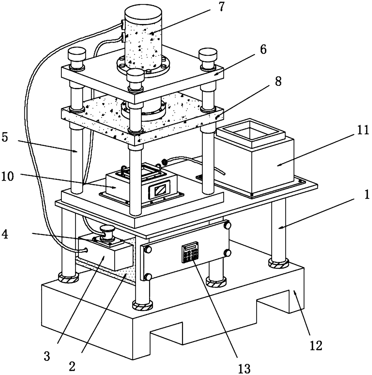
[0027] see Figure 1-7 , in the embodiment of the present invention,

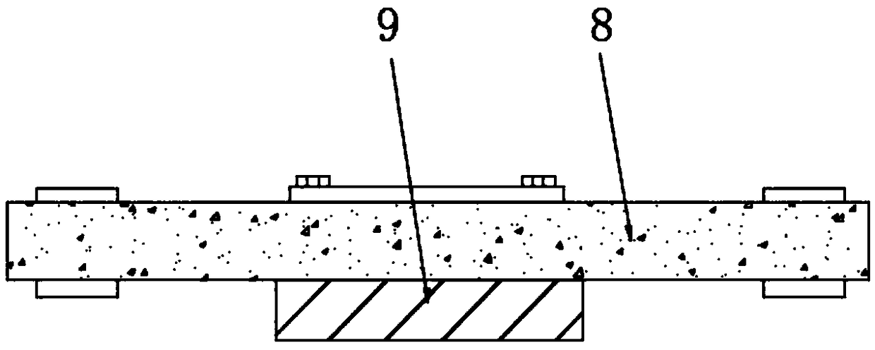
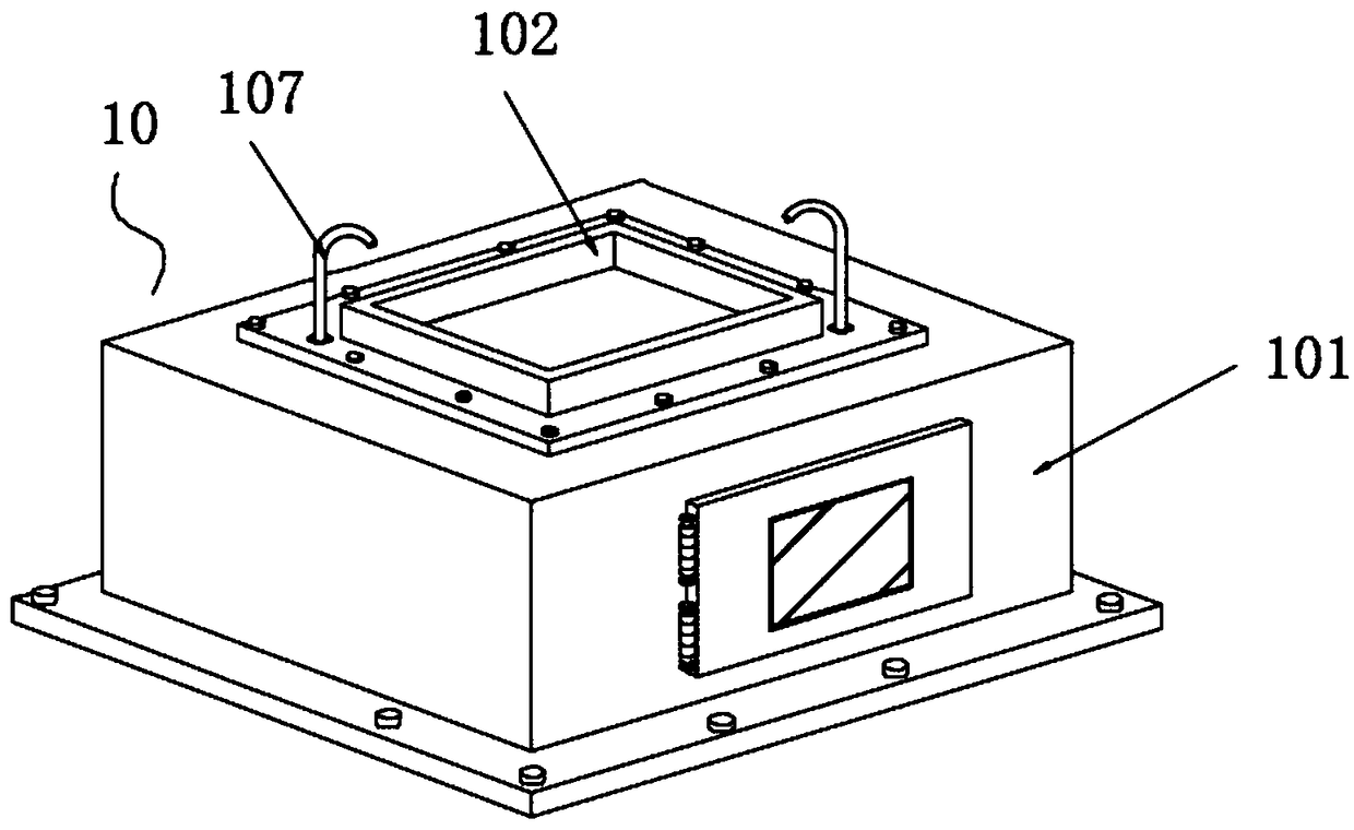
[0028] see Figure 1~2 , a construction waste treatment device for civil engineering, comprising a working platform 1, a pressure-bearing platform 2 is fixedly installed at the bottom of the inner side of the four supporting legs of the working platform 1, and a pressure-bearing platform 2 is fixedly installed on the upper surface of the pressure-bearing platform 2 for storing hydraulic pressure. An oil storage tank 3, the upper surface of the oil storage tank 3 is fixedly equipped with an oil pump 4, and the upper surface of the working platform 1 is fixedly installed with a guide rail 5. There are four guide rails 5 arranged in a rectangular distribution. The upper end of the guide rail 5 is fixed outside the sleeve Connected with a fixed plate 6, the upper surface of the fixed plate 6 is fixedly installed with a hydraulic jack 7, the liquid outlet of the oil storage tank 3 is connected with the liquid i...


PUM


Abstract

The invention discloses a construction waste treatment device for civil engineering. The construction waste treatment device comprises a working platform, a pressure-bearing table board is fixedly installed at the bottoms of the inner sides of four supporting legs of the working platform, and the upper surface of the pressure-bearing table surface is fixedly provided with an oil storage tank usedfor storing hydraulic oil; and an oil pump is fixedly installed on the upper surface of the oil storage tank, guide rails are fixedly installed on the upper surface of the working platform, and four guide rails are arranged. A dust removal mechanism is added into a die-cast area of a die-casting device of concrete waste, so that dust generated in a die casting process can be effectively absorbed and treated; a forming mechanism is installed on a workbench surface, the concrete waste can be effectively formed and processed, a pump body and a pipeline which can be added with a concrete adhesiveare arranged in the forming mechanism, the concrete adhesive is sprayed into a forming box body, the bonding force of the concrete in the die casting process can be improved, and the quality of die casting is improved.

Description

technical field [0001] The invention relates to the technical field of construction waste treatment, in particular to a construction waste treatment device for civil engineering. Background technique [0002] Construction waste, also known as construction waste, and construction waste refers to the dregs and spoils generated during the construction, laying or demolition, and repair of various buildings, structures, pipe networks, etc. by construction units or individuals , discarded material, silt and other wastes. In construction waste, waste concrete occupies a large proportion. Therefore, it is necessary to screen, crush and die-cast this part of waste concrete. Among them, the die-casting process of concrete requires This is done with the help of a die-casting device. [0003] However, the currently commonly used concrete waste treatment die-casting device is not only complex in structure, but also has a single function. During the die-casting process of concrete waste,...

Claims


Application Information

Patent Timeline
Patent Type & Authority Applications(China)
IPC IPC(8): B28B3/00B28B17/04
CPCB28B3/00B28B17/04
Inventor 张玉涛杜斌郭仔翔车小林沈明轩
Owner GUIZHOU UNIV
Why Eureka
Try Eureka