
Automatic fiber arranging device

A sorting device and fiber technology, which is applied to the parts and components of the strapping machine, can solve the problems of not being able to carry out tight strapping in time, easy to loose during storage, etc., and achieve stability, high efficiency, strong continuity, and high stability Effect

Inactive Publication Date: 2019-01-08
CHANGXING HAIPU MACHINERY TECH CO LTD
View PDF1 Cites 2 Cited by
  • Summary
  • Abstract
  • Description
  • Claims
  • Application Information

AI Technical Summary

Problems solved by technology

[0005] The purpose of the present invention is to address the deficiencies of the prior art. By setting the first transmission mechanism, the U-shaped iron wires equipped with fiber bundles are horizontally and sequentially conveyed continuously, and then the U-shaped iron wires below the path are longitudinally driven by the clamping assembly. The iron wire is clamped, and then along with the transmission of the longitudinal drive component, the tightening component tightens and binds the U-shaped iron wire on the clamping component, thus solving the problem that the fiber cannot be tightly bundled in time after collection, and it is easy to loosen during storage. The problem is that it has a simple structure, is easy to use, and can realize mechanized fiber collection. This method does not cause any damage to the fibers and improves work efficiency.

Method used


Image

  • Automatic fiber arranging device
  • Automatic fiber arranging device
  • Automatic fiber arranging device

Examples


Embodiment 1

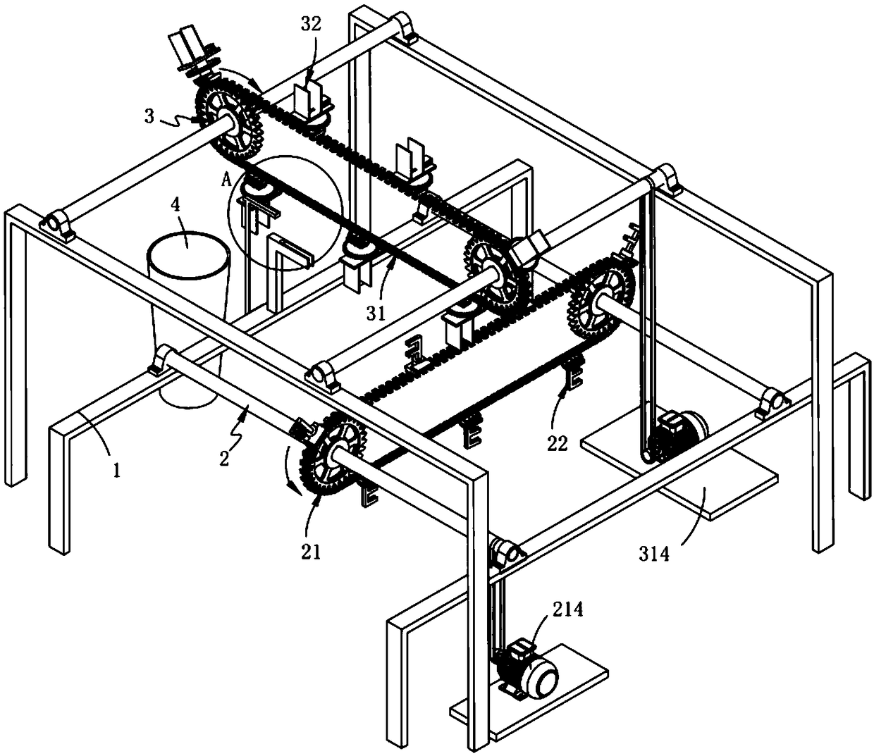
[0062] Such as figure 1 Shown, a kind of automatic fiber finishing device comprises:

[0063] Rack 1;

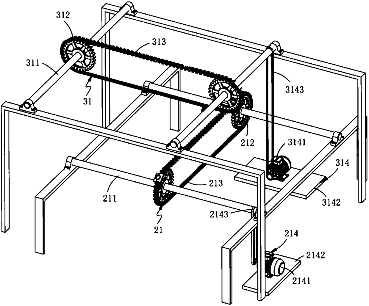
[0064] The first transmission mechanism 2, the first transmission mechanism 2 is fixedly arranged on the frame 1, which includes a lateral drive assembly 21 and a feeding assembly 22 arranged on the lateral drive assembly 21;

[0065] The second transmission mechanism 3, the second transmission mechanism 3 is fixedly arranged on the frame 1 and arranged above the first transmission mechanism 2, which includes a longitudinal drive assembly 31 vertically arranged with the horizontal drive assembly 21 , a clamping component 32 arranged on the longitudinal drive component 31 and a tightening component 33 cooperating with the clamping component 32; and

[0066] The discharge bucket 4 is arranged on the frame 1 and located at the rear end of the longitudinal drive assembly 31 .

[0067] In this embodiment, the U-shaped iron wires equipped with fiber bundles are horizontally and...

Embodiment 2

[0109] Such as image 3 As shown, the components that are the same as or corresponding to those in the first embodiment are marked with the corresponding reference numerals in the first embodiment. For the sake of simplicity, only the differences from the first embodiment will be described below. The difference between this embodiment two and embodiment one is:

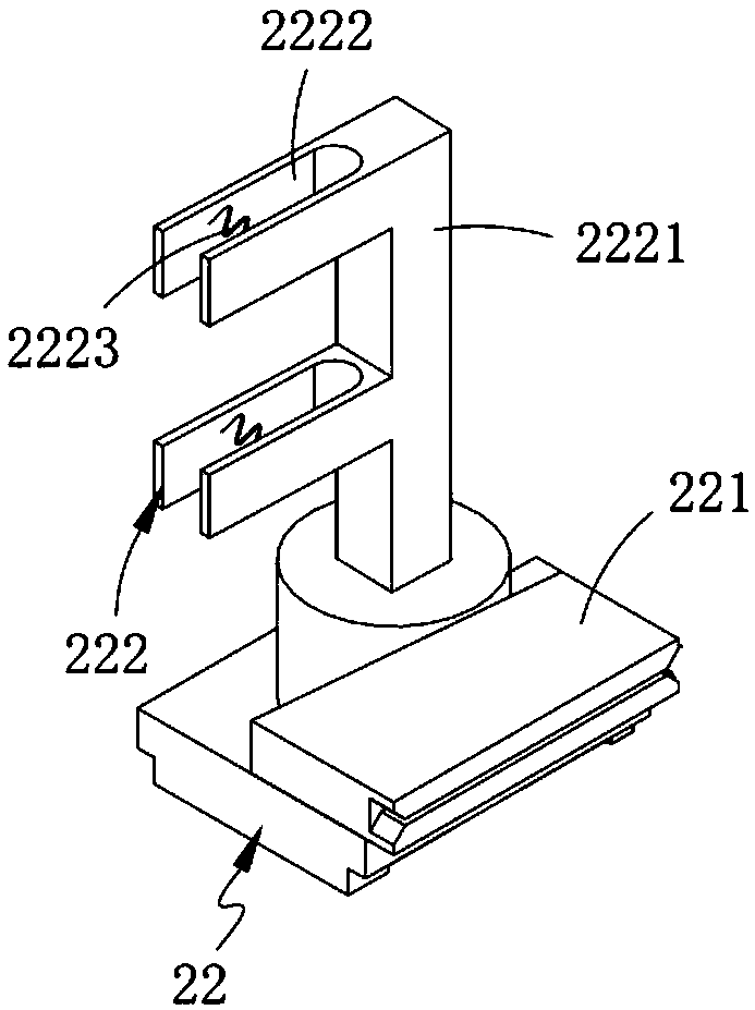
[0110] further, such as image 3 As shown, the locking groove 2222 is further provided with a spring 2223 , and the spring 2223 is arranged along the width direction of the locking groove 2222 .

[0111] In this embodiment, by setting the spring 2223, on the one hand, the locking groove 2222 can fix the iron wire; During the process, it is in direct contact with the fiber bundle to ensure the quality of the fiber bundle.

[0112] work process:

[0113]Start the driving part 214, manually place the fiber bundle in the iron wire, and then manually continue to place the iron wire in the locking groove 2222, and with ...


PUM


Abstract

The invention relates to an automatic fiber arranging device. The device comprises a machine frame, a first transmission mechanism, a second transmission mechanism and a discharging cylinder, whereinthe first transmission mechanism is fixedly arranged on the machine frame, and the first transmission mechanism comprises a transverse driving assembly and a feeding assembly arranged on the transverse driving mechanism; the second transmission mechanism is fixedly arranged on the machine and is arranged above the first transmission mechanism, and comprises a longitudinal driving assembly which isvertically arranged with the transverse driving assembly, a clamping assembly arranged on the longitudinal driving assembly and a tightening assembly matched with the clamping assembly for transmission; and the discharging cylinder is arranged on the machine frame and is located at the tail end of the longitudinal driving assembly. According to the automatic fiber arranging device, the technicalproblems that after fibers are collected, tight binding arrangement cannot be carried out in time, and the fibers are prone to loosing in the storage process are solved; and the structure is simple, the fibers can be orderly and mechanically collected, damage to the fibers is avoided, and the working efficiency is improved.

Description

technical field [0001] The invention relates to the technical field of fiber finishing, in particular to an automatic fiber finishing device. Background technique [0002] In the production and life of using fibers as raw materials, an important and extensive production process is to obtain relatively neat fiber bundles, especially in industries closely related to people's production and life, such as civil brush industry, clothing industry, hair product industry, etc. It is an animal fiber in the hair product industry and a functional fiber in a special industry. In order to get the real feel and look of real hair from the fiber, it is necessary to straighten and pat the fiber. [0003] Patent No. CN103590160A discloses a device and method for extracting fibers from fiber bundles and collecting them neatly. Positioning system; one end of the positioning platform is connected to one side of the frame, and the other end of the positioning platform is fixed on the other side ...

Claims


Application Information

Patent Timeline
Patent Type & Authority Applications(China)
IPC IPC(8): B65B13/28
CPCB65B13/28
Inventor 倪瑞华
Owner CHANGXING HAIPU MACHINERY TECH CO LTD
Learn More