Brake drum device for automobile

A technology for brake drums and automobiles, applied in the direction of brake drums, mechanical equipment, brake types, etc., can solve problems such as brake pad thermal degradation, and achieve the effect of temperature stability

Pending Publication Date: 2019-01-08
南京布雷尔汽车配件有限公司
View PDF0 Cites 1 Cited by
  • Summary
  • Abstract
  • Description
  • Claims
  • Application Information

AI Technical Summary

Problems solved by technology

[0004] The purpose of the present invention is to provide a brake drum device for automobiles to solve the problem of thermal fading of the brake pads due to high temperature in the above-mentioned background technology

Method used


Image

  • Brake drum device for automobile
  • Brake drum device for automobile
  • Brake drum device for automobile

Examples


Embodiment Construction

[0021] The technical solutions in the embodiments of the present invention will be clearly and completely described below in conjunction with the accompanying drawings in the embodiments of the present invention. Obviously, the described embodiments are only a part of the embodiments of the present invention, rather than all the embodiments.

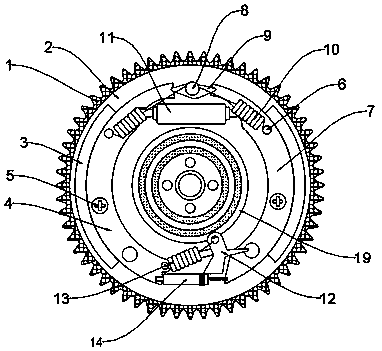
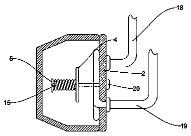
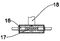
[0022] See Figure 1-4 , An embodiment provided by the present invention: a brake drum device for an automobile, comprising a brake drum 1, an inner drum chassis 2 is installed on the inner side of the brake drum 1, and a frozen water pipe is installed on the bottom surface of the inner drum chassis 2 19. A front brake shoe 4 is installed on one side of the chilled water pipe 19, a rear brake shoe 7 is installed on the other side of the chilled water pipe 19, and one of the top ends of the front brake shoe 4 The main limit plate 9 is installed on the side, and the brake cylinder 11 is installed below the main limit plate 9. The hydraulic oi...


PUM


Abstract

The invention discloses a brake drum device for an automobile. The device comprises a brake drum body, and is characterized in that the inner side of the brake drum is provided with an drum inner bottom plate, the bottom surface of the drum inner bottom plate is provided with a chilled water pipeline, one side of the chilled water pipeline is provided with a front brake shoe sheet, and the other side of the chilled water pipeline is provided with a rear brake shoe sheet; a main limiting board is installed on one side of the top end of the front brake shoe sheet, a brake branch pump is installed below the main limiting board, return spring bolts are installed at the top end of the main limiting board, and return spring limiting holes are both formed in the front end face of the front brakeshoe sheet and the front end face of the rear brake shoe sheet; and the return spring limiting holes are connected with the return spring bolts through return springs, and ceramic fiber brake pieces are both installed on the outer side of the front brake shoe sheet and the outer side of the rear brake shoe sheet. According to the device, due to the fact that the chilled water pipe is installed inthe drum inner bottom plate, a harmful effect of overheating expansion of the whole device is avoided.

Description

Technical field [0001] The invention relates to the technical field of drum brakes, in particular to a brake drum device for automobiles. Background technique [0002] Drum brakes have been used in automobiles for nearly a century, but due to its reliability and powerful braking force, drum brakes are still installed on many models (mostly used on the rear wheels). It is fixed to the tire and rotates at the same speed. When braking, hydraulic pressure is used to push the brake shoe into contact with the inner edge of the brake drum, and the friction generated by the contact can restrain the rotation of the tire to achieve the purpose of braking. The drum brake is composed of the brake bottom plate, brake cylinder, brake shoe and other related connecting rods, springs, pin nails, and brake drum. Currently, it is generally installed on the rear wheel. Drum brakes have lower cost and higher absolute braking power. The inner surface of the brake drum of drum brakes is where the br...

Claims


Application Information

Patent Timeline
Patent Type & Authority Applications(China)
IPC IPC(8): F16D65/10F16D65/09F16D65/833F16D65/40F16D65/14F16D121/04
CPCF16D65/10F16D65/09F16D65/14F16D65/40F16D65/833F16D2121/04
Inventor 李新明
Owner 南京布雷尔汽车配件有限公司
Why Eureka
Try Eureka