
Rope tightness adjusting part and application thereof

An elastic adjustment and rope technology, which is applied in the field of mechanical environment test, can solve the problems of breaking off or being stretched and detached, cracking of movable parts, affecting work efficiency, etc. Effect

Pending Publication Date: 2019-01-08
SUZHOU DONGLING VIBRATION TEST INSTR
View PDF1 Cites 5 Cited by
  • Summary
  • Abstract
  • Description
  • Claims
  • Application Information

AI Technical Summary

Problems solved by technology

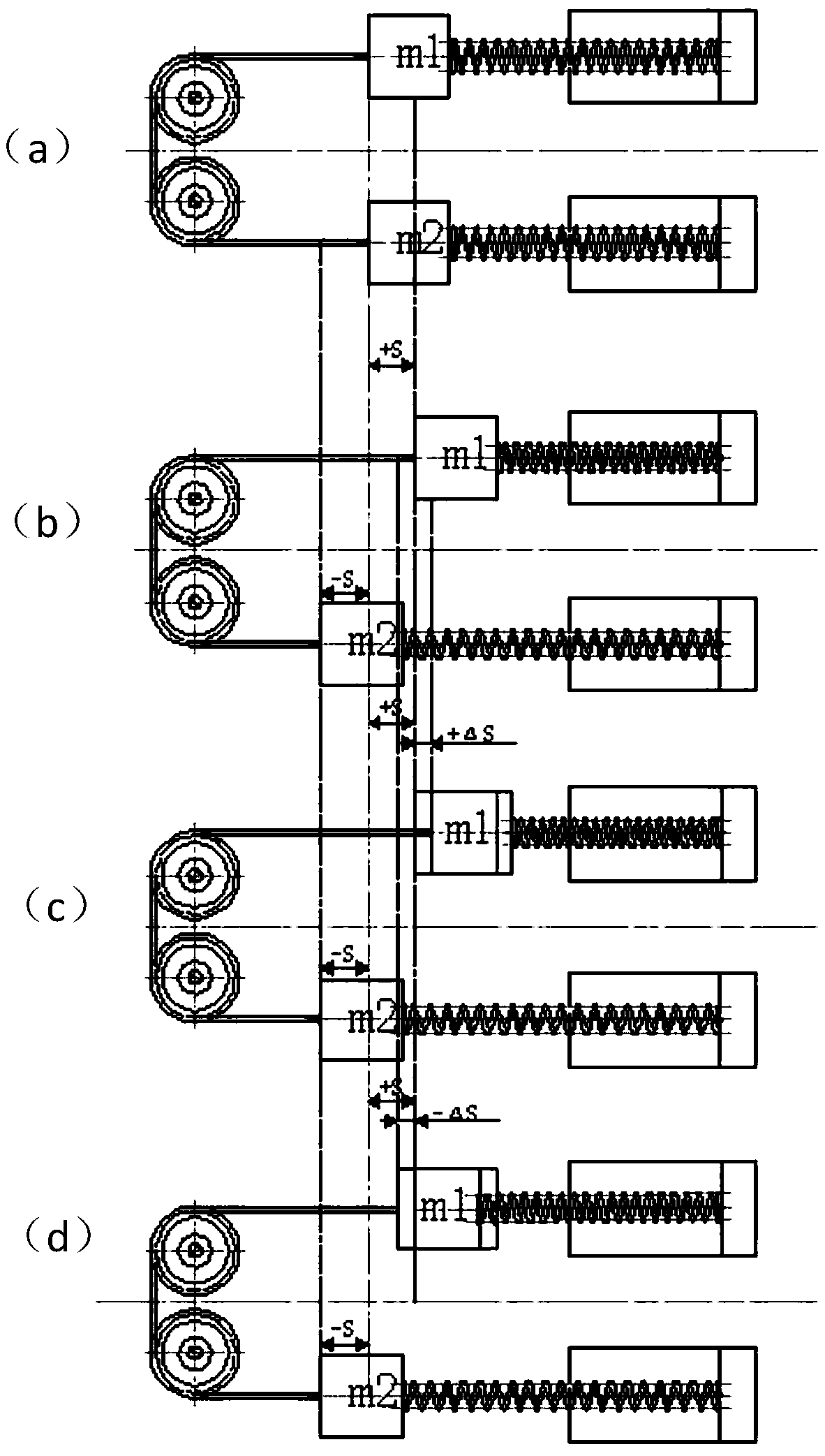
like figure 1 -As shown in (a), it is the initial state of the balance device; figure 1 -As shown in (b), when the moving parts of the two vibration generators are excited by the driving force Fsinwt of equal size and opposite direction, the movement of the moving parts in the ideal state; it may appear in the actual process figure 1 - For the motion shown in (c), at this time, since the design length of the rope itself is fixed, the rope will either be deformed and elongated, and after the error accumulates, the rope will be broken, or the movable parts will be damaged and cracked; or figure 1 - In the case shown in (d), at this time, the rope will be in a slack state, and the rope may be directly disengaged from the pulley groove, which cannot play the role of balancing the centrifugal force of the moving parts
To sum up, after the centrifuge rotates, the rope in the balance mechanism will sometimes be broken or loosened and elongated, and then break away from the designed groove track. In severe cases, the moving parts on the vibration generator will be damaged, affecting the work. efficiency, causing equipment damage

Method used


Image

  • Rope tightness adjusting part and application thereof
  • Rope tightness adjusting part and application thereof
  • Rope tightness adjusting part and application thereof

Examples


Embodiment Construction

[0028] The present invention will be further described below in conjunction with the accompanying drawings and specific embodiments, so that those skilled in the art can better understand the present invention and implement it, but the examples given are not intended to limit the present invention.

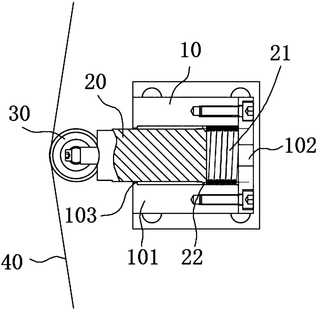
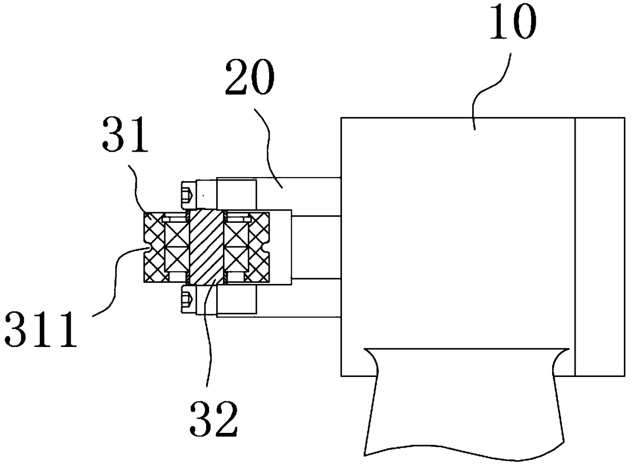
[0029] refer to Figure 2-Figure 3 As shown, the present invention discloses a rope tightness adjusting part, the rope tightness adjusting part includes a spring 21, a guide rod 20 and a mounting base 10, a guiding groove is opened inside the mounting base 10, and the spring 21 is arranged in the guiding groove, and The tail of the spring 21 abuts against the groove wall of the guide groove. One end of the guide rod 20 passes through the guide groove and abuts against the head of the spring 21 , and the other end of the guide rod 20 protrudes from the guide groove and abuts against the rope 40 . Under the action of the spring 21, the guide rod 20 will move in the guide groove aft...


PUM


Abstract

The invention discloses a rope tightness adjusting part and an application thereof. The rope tightness adjusting part comprises a spring, a guide rod and a mounting base, wherein a guide groove is formed inside the mounting base, the spring is arranged in the guide groove, and the tail part of the spring abuts against a groove wall of the guide groove; one end of the guide rod penetrates through the guide groove and abuts against a head part of the spring, and the other end of the guide rod extends out of the guide groove and abuts against the rope; the guide rod slides along the guide grooveunder the action force of the rope so as to adjust the tightness of the rope; and the rope tightness adjusting part can be applied to an anti-loose balance device and a centrifugal vibration equipment. Self-adaptive adjustment can be carried out on the rope according to the tightness of the rope by the rope tightness adjusting part, so that a method is simple, the practicability is high, and an effect is good.

Description

technical field [0001] The invention relates to the technical field of mechanical environmental tests, in particular to a rope tension adjusting component and its application. Background technique [0002] Centrifugal shaking table equipment is a kind of mechanical environment test equipment mainly used for the reliability test of the whole machine or parts of large-scale products in aerospace, aviation and other departments. Special purpose in construction, earthquake and other sectors. The centrifugal shaking table equipment is mainly composed of a centrifuge test system, a shaking table test system, and an auxiliary control system. [0003] For the elastic motion components working in the centrifugal field, the moving parts are inevitably affected by the centrifugal force. When the elastic motion system reciprocates in the radial direction of the rotating shaft in the centrifugal field, with the rotation angular velocity in the centrifugal field Different, the magnitude...

Claims


Application Information

Patent Timeline
Patent Type & Authority Applications(China)
IPC IPC(8): F16F15/20G01M7/02
CPCF16F15/20G01M7/02
Inventor 王丽娟仝宁可胥小强
Owner SUZHOU DONGLING VIBRATION TEST INSTR
Learn More