
Micro tiller applied to different soil conditions and different dryland operation needs and control method

A control method and micro tillage machine technology, which is applied in the fields of application, tillage implements, agricultural machinery and implements, etc., can solve problems such as micro tillage machines are easily injured and operators, difficult to control tillage speed, and large difference in effects, etc., and achieve backward The effect of slowing down the speed, not easy to deviate, and stabilizing the overall center of gravity

Pending Publication Date: 2019-01-11
TONGHAI DASEN IND & TRADE
View PDF2 Cites 1 Cited by
  • Summary
  • Abstract
  • Description
  • Claims
  • Application Information

AI Technical Summary

Problems solved by technology

[0007] In the prior art, it is difficult to control the tillage speed of the micro-tiller, and the operator consumes a lot of physical strength to control the tiller. The effect of the tiller on different soil types is quite different, and the tiller is easy to injure the operator when it retreats.

Method used


Image

  • Micro tiller applied to different soil conditions and different dryland operation needs and control method
  • Micro tiller applied to different soil conditions and different dryland operation needs and control method
  • Micro tiller applied to different soil conditions and different dryland operation needs and control method

Examples


Embodiment Construction

[0038] In order to make the object, technical solution and advantages of the present invention more clear, the present invention will be further described in detail below in conjunction with the examples. It should be understood that the specific embodiments described here are only used to explain the present invention, not to limit the present invention.

[0039] In the prior art, it is difficult to control the tillage speed of the micro-tiller, and the operator consumes a lot of physical strength to control the tiller. The effect of the tiller on different soil types is quite different, and the tiller is easy to injure the operator when it retreats.

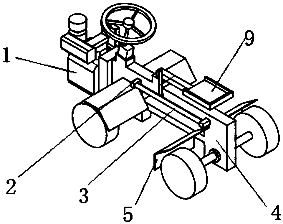
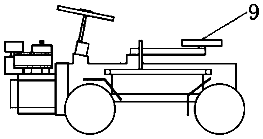
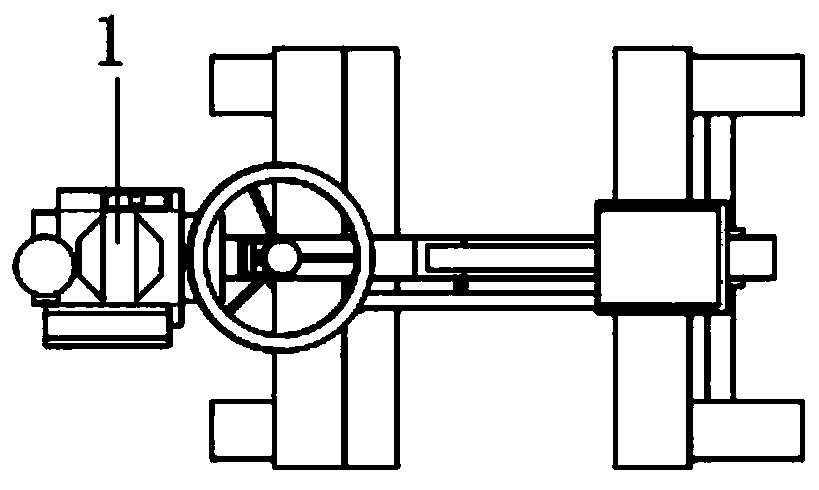
[0040] like Figure 1-Figure 5 As shown, the tiller provided by the embodiment of the present invention includes:

[0041] Tiller gearbox 1,

[0042] The output shaft head 2 on the side of the tiller gearbox 1 transmits the power to the worm 3;

[0043] The worm 3 transmits power to the constant speed rotating wheel 4 throug...


PUM


Abstract

The invention belongs to the technical field of agricultural machineries, and discloses a micro tiller applied to different soil conditions and different dryland operation needs and a control method.When the blade of the micro tiller tills to hard soil, the ground grasping plate of a constant speed rotating wheel cuts into the ground, the forward impulse of the blade is restricted by the ground grasping plate, the advancing speed of the blade slows down, and the in-situ tilling times are increased; when the blade of the micro tiller tills to soft soil and the blade sinks, a soil grasping plate performs constant-speed forward pushing to enable the blade to be away from the sunken soil layer to continue forward tilling; when the blade sinks into a ditch or a pot hole, through pressing a seat, the soil grasping plate provides thrust to push the micro tiller out of the ditch or the pot hole; and when the micro tiller reverses, the ground grasping plate on the constant speed rotating wheelperforms low-rotating speed limiting, and the micro tiller retreats and slows down. The micro tiller applied to different soil conditions and different dryland operation needs is suitable for stickysoil and other soil areas and has the advantages of simple structure, compact structure, light weight, low fuel consumption, high efficiency, flexible operation, convenient maintenance and reliable operation.

Description

technical field [0001] The invention belongs to the technical field of agricultural machinery and equipment, and in particular relates to a micro tillage machine and a control method applied to different soil conditions and different operation needs. Background technique [0002] At present, the existing technologies commonly used in the industry are as follows: [0003] The micro tillage machine in the prior art is composed of a frame, an engine, a gearbox, a transmission box, a cultivating knife and a seat. When using this micro tiller, the operator needs to hold the handle on the seat to control the tiller. During the working process of the micro-tiller, when the tiller rotates and cuts into the ground, the resistance is relatively large, and the body vibrates strongly, which may easily cause the micro-tiller to deviate from the farming route. The operator needs to use a large force to hold the micro-tiller in order to maintain the normal tillage state. Hold the handle; ...

Claims


Application Information

Patent Timeline
Patent Type & Authority Applications(China)
IPC IPC(8): A01B33/00A01B33/08A01B33/10A01B33/12
CPCA01B33/00A01B33/082A01B33/10A01B33/12
Inventor 张涛普发团王仲林白家富张翼周昆李谦资玉波陈洪震
Owner TONGHAI DASEN IND & TRADE
Learn More