Intervertebral fusion cage and an installation tool thereof

An intervertebral fusion cage and installation tool technology, applied in medical science, prosthesis, joint implants, etc., can solve the problems of slow fusion speed, poor stability, poor fusion effect, etc., and achieve easy operation, high support and stability , the effect of simple structure

Pending Publication Date: 2019-01-11
北京东鸿致远医疗科技有限公司
View PDF0 Cites 3 Cited by
  • Summary
  • Abstract
  • Description
  • Claims
  • Application Information

AI Technical Summary

Problems solved by technology

However, the design of the existing intervertebral fusion device is unreasonable. Since the end faces of adjacent vertebral bodies are not parallel to each other, the existing intervertebral fusion device cannot completely contact the end face of the vertebral body, and the stability is poor;
[0004] In addition, after the existing intervertebral fusion cage is stretched, because the volume becomes larger, the pre-filled broken bone cannot contact the end surface of the vertebral body, so the fusion speed is slow and the fusion effect is poor

Method used


Image

  • Intervertebral fusion cage and an installation tool thereof
  • Intervertebral fusion cage and an installation tool thereof
  • Intervertebral fusion cage and an installation tool thereof

Examples


Embodiment Construction

[0033] The embodiments described below by referring to the figures are exemplary only for explaining the present invention and should not be construed as limiting the present invention.

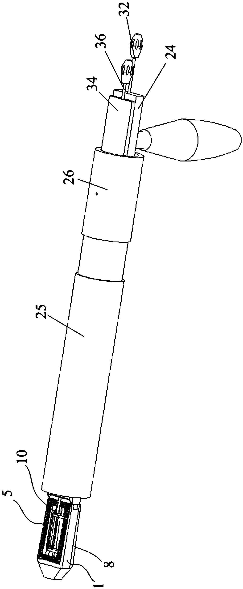
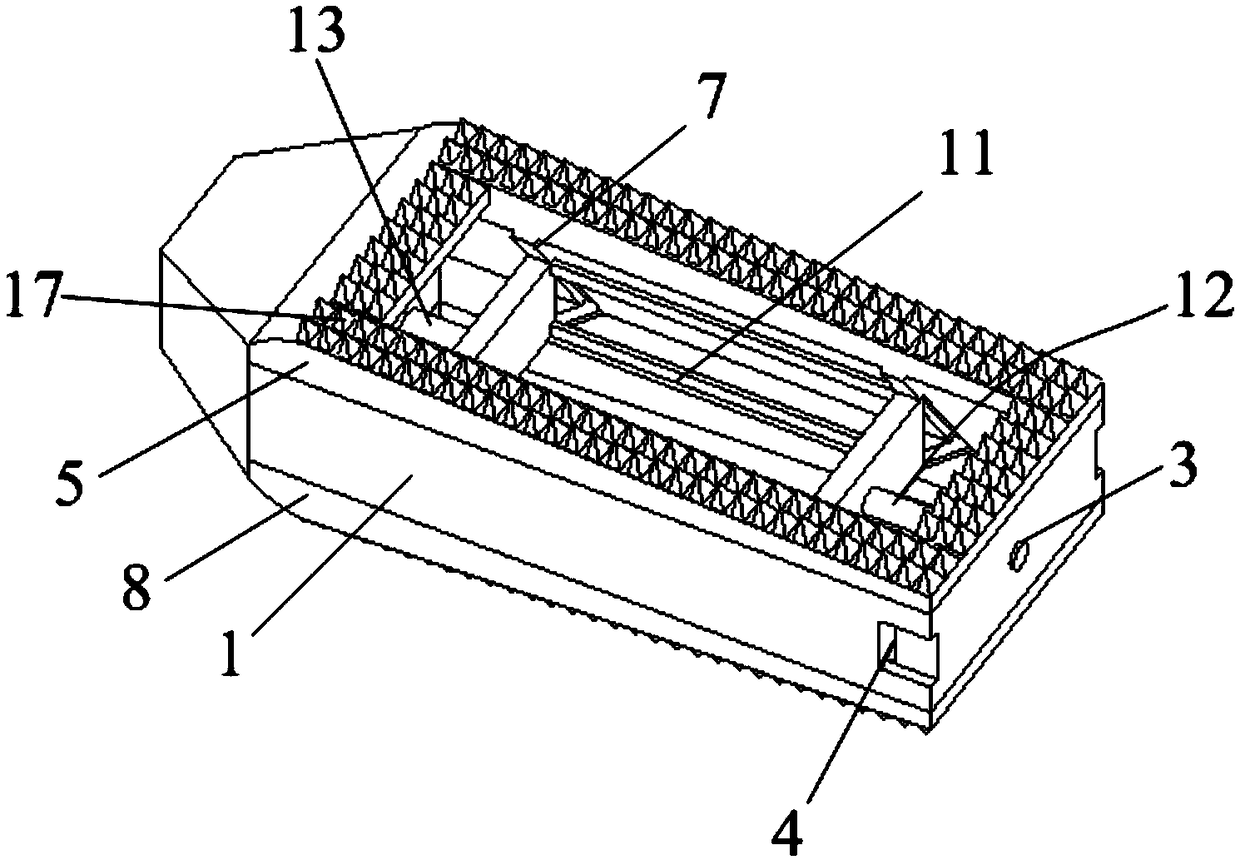
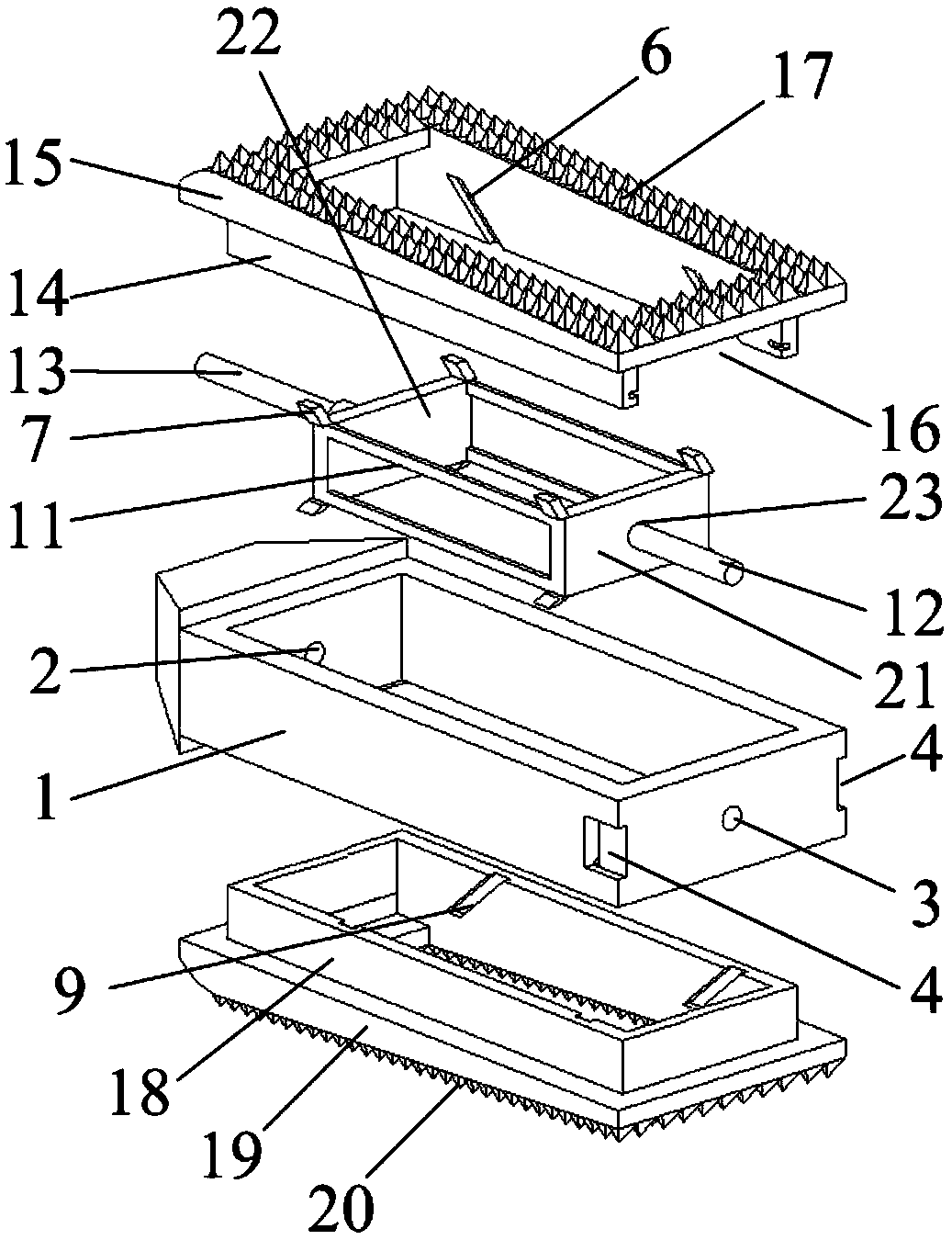
[0034] Embodiments of the present invention: a kind of intervertebral fusion device, such as figure 2 with image 3 shown, including,

[0035] Frame body 1, its outer contour is roughly rectangular parallelepiped, top and bottom are open structure, and its one end is provided with light hole 2, and the other end is provided with threaded hole 3, and the two outer walls of one end provided with threaded hole 3 are provided with The clamping groove 4 preferably adopts an L-shaped structure; in order to prevent the present invention from injuring tissues and organs in the human body during implantation, it is preferable to set a cone at the end of the frame 1 with the light hole 2 Shaped end, the edges and corners of the tapered end are all rounded.

[0036] The first support body 5 is slida...


PUM


Abstract

The invention discloses an intervertebral fusion cage and a mounting tool thereof. The intervertebral fusion cage comprises a frame body, a first support body, a second support body and a driving mechanism. One end of the frame body is provided with a light hole, the other end is provided with a threaded hole, and two outer side walls provided with a threaded hole are provided with clamping grooves. A first inclined slide way is arranged on the inner wall of the first support body; A second inclined slide way is arranged on the inner wall of the second support body; A drive mechanism includesa drive frame, an adjustment mechanism, and a guide rod. When the drive frame slides within the frame, the first support body and the second support body are driven away from each other or close to each other. The mounting tool comprises a plier body, a movable sleeve, an adjusting sleeve and an adjusting rod. Two elastic clamping rods arranged in parallel are arranged at one end of the plier body, and the free ends of the two elastic clamping rods are provided with a hook body engaged with a clamping groove. The invention has the advantages of better support stability, convenient implantationand convenient operation.

Description

technical field [0001] The invention relates to an intervertebral fusion device and an installation tool thereof, belonging to the field of medical instruments. Background technique [0002] In the prior art, as people grow older, have physical lesions or sit in the office for a long time, it is easy to cause spinal degenerative diseases. The common degenerative diseases of the spine include intervertebral disc degeneration, spinal stenosis, spondylolisthesis, and compression of the spinal cord or nerve roots. These diseases often require surgical treatment to completely relieve the compression, restore the physiological curvature of the spine, and ensure spinal stability. [0003] Existing treatment methods usually use an intervertebral fusion device, which has a good curative effect on the above spinal diseases. However, the design of the existing intervertebral fusion device is unreasonable. Since the end faces of adjacent vertebral bodies are not parallel to each other,...

Claims


Application Information

Patent Timeline
Patent Type & Authority Applications(China)
IPC IPC(8): A61F2/46A61F2/44
CPCA61F2/4611A61F2/4455A61F2002/4687A61F2002/4688A61F2250/0058
Inventor 雷东
Owner 北京东鸿致远医疗科技有限公司
Why Eureka
Try Eureka