Dynamic detection method and detection device of peak expiratory flow meter
A detection device and dynamic detection technology, applied in the direction of respirators, medical devices, and other medical devices, can solve the problem of metal fatigue of elastic components, affecting measurement accuracy, and the detection method of peak expiratory flow rate without a peak expiratory flow meter Instrument and other problems, to achieve accurate test results, stable and reliable operation, and low production costs
- Summary
- Abstract
- Description
- Claims
- Application Information
AI Technical Summary
Problems solved by technology
Method used
Image
Examples
Embodiment 1
[0048] A dynamic detection method of a peak expiratory flow meter, comprising the following steps:
[0049] 1) simulate the exhalation step, perform three simulated exhalations by the peak expiratory flow meter detection device to be detected, obtain three analog measurement result waveforms and three detection airflow waveforms, including the following sub-steps:
[0050] 1.1) Preset the simulated exhalation step, and set the simulated exhalation mode of three flow rate time ratios through the control unit of the peak expiratory flow meter detection device, so as to realize the control of the dynamic gas supply device in the peak expiratory flow meter detection device Generate three detection airflows matching the simulated exhalation mode, and the generation interval between each detection airflow is preferably 2 seconds;
[0051] 1.2) In the step of obtaining feedback data, airtightly connect the air volume interface 11 of the dynamic air supply device of the peak expirator...
Embodiment 2
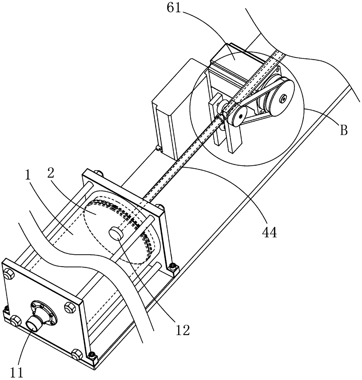
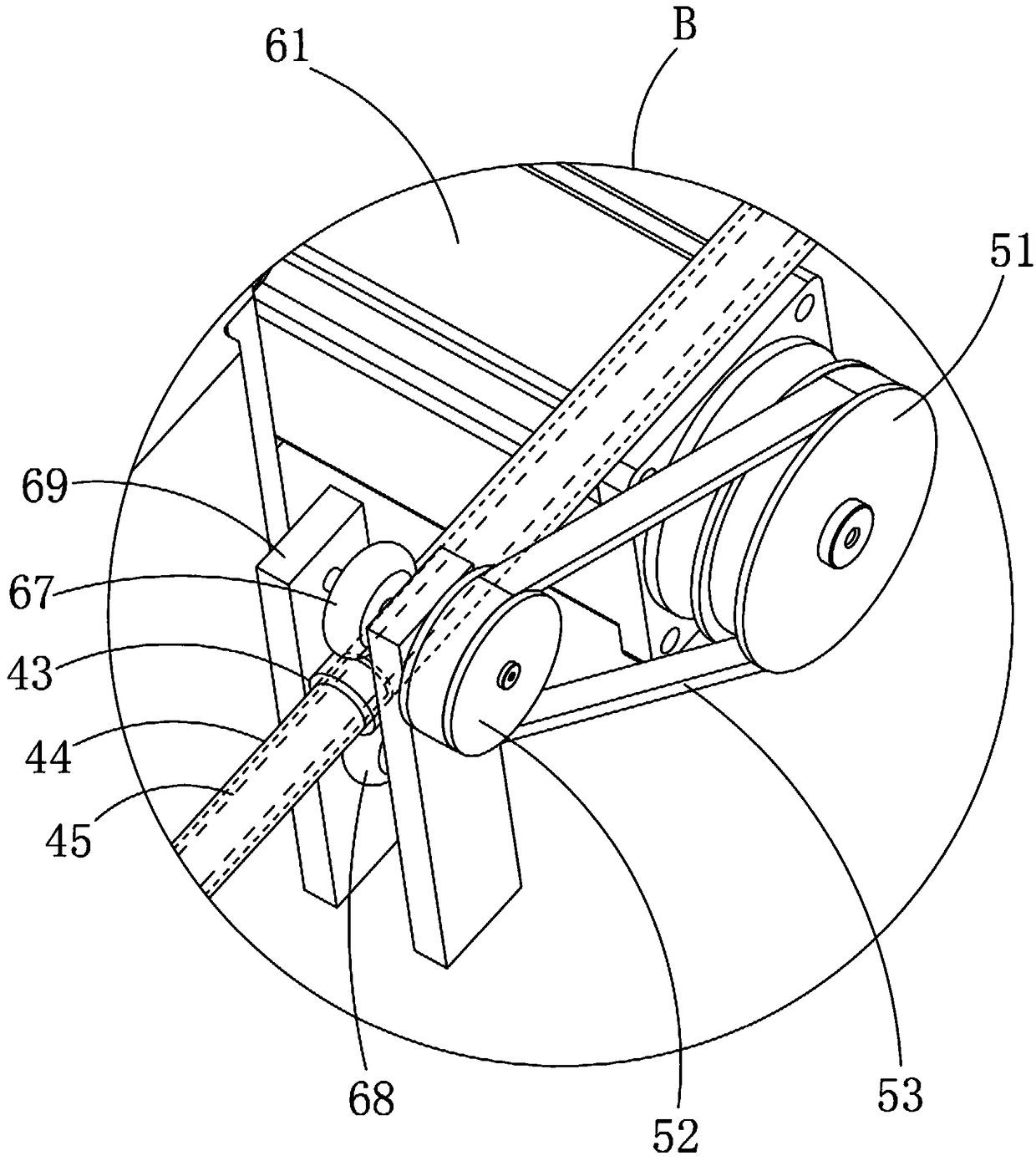
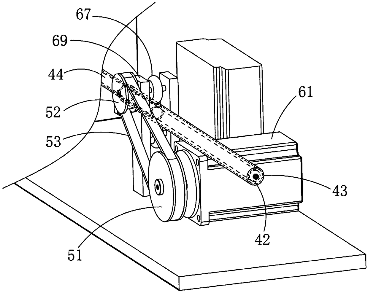
[0058] A kind of peak expiratory flow meter detection device, see Figure 1 to Figure 6 As shown, it includes a dynamic air supply device. The dynamic air supply device includes an air cylinder 1, an air volume interface 11 connected to the front end of the air cylinder 1, a piston 2 slidably installed in the air cylinder 1, and a piston drive mechanism that is connected to the piston 2 by transmission. The piston drive mechanism Including a servo motor 61 and a belt transmission mechanism, the rear end of the gas cylinder 1 is fixed with a guide tube 44; the middle of the rear end of the piston 2 is fixed with a polished rod 45, and the polished rod 45 is slidably inserted into the inner cavity of the guide tube 44, and the polished rod 45 The rear end passes through the guide tube 44 and extends to the outside of the guide tube 44; the guide tube 44 is slidably fitted with a drive tube 43, the rear end of the drive tube 43 is fixed on the rear end of the polished rod 45, and ...
PUM
 Abstract
Description
Claims
Application Information
 - R&D
- Intellectual Property
- Life Sciences
- Materials
- Tech Scout
- Unparalleled Data Quality
- Higher Quality Content
- 60% Fewer Hallucinations
Browse by: Latest US Patents, China's latest patents, Technical Efficacy Thesaurus, Application Domain, Technology Topic, Popular Technical Reports.
© 2025 PatSnap. All rights reserved.Legal|Privacy policy|Modern Slavery Act Transparency Statement|Sitemap|About US| Contact US: help@patsnap.com


