Perforating device capable of achieving automatic and rapid perforating

A drilling device and transmission technology, applied in the direction of boring/drilling, drilling/drilling equipment, maintenance and safety accessories, etc., can solve the problems of reduced efficiency, reduced efficiency, small waste volume, etc., and achieve faster drilling Hole speed, reduction of production cost, effect of fast drilling operation

Inactive Publication Date: 2019-01-11
黄钟葳
View PDF0 Cites 0 Cited by
  • Summary
  • Abstract
  • Description
  • Claims
  • Application Information

AI Technical Summary

Problems solved by technology

The automatic punching machine prints the positioning hole, the whole action is done in one go, fast, accurate, and high in efficiency. Now the punching machine on the market is a drill, so the efficiency of punching will be greatly reduced, thereby reducing the production efficiency. The high-end punching machines are not equipped with shock absorbing devices. Over time, it is easy to reduce the service life of its internal precision parts, and the general punching machine will generate a large amount of wind waste, which is small in size and difficult to collect.

Method used


Image

  • Perforating device capable of achieving automatic and rapid perforating
  • Perforating device capable of achieving automatic and rapid perforating
  • Perforating device capable of achieving automatic and rapid perforating

Examples


Embodiment

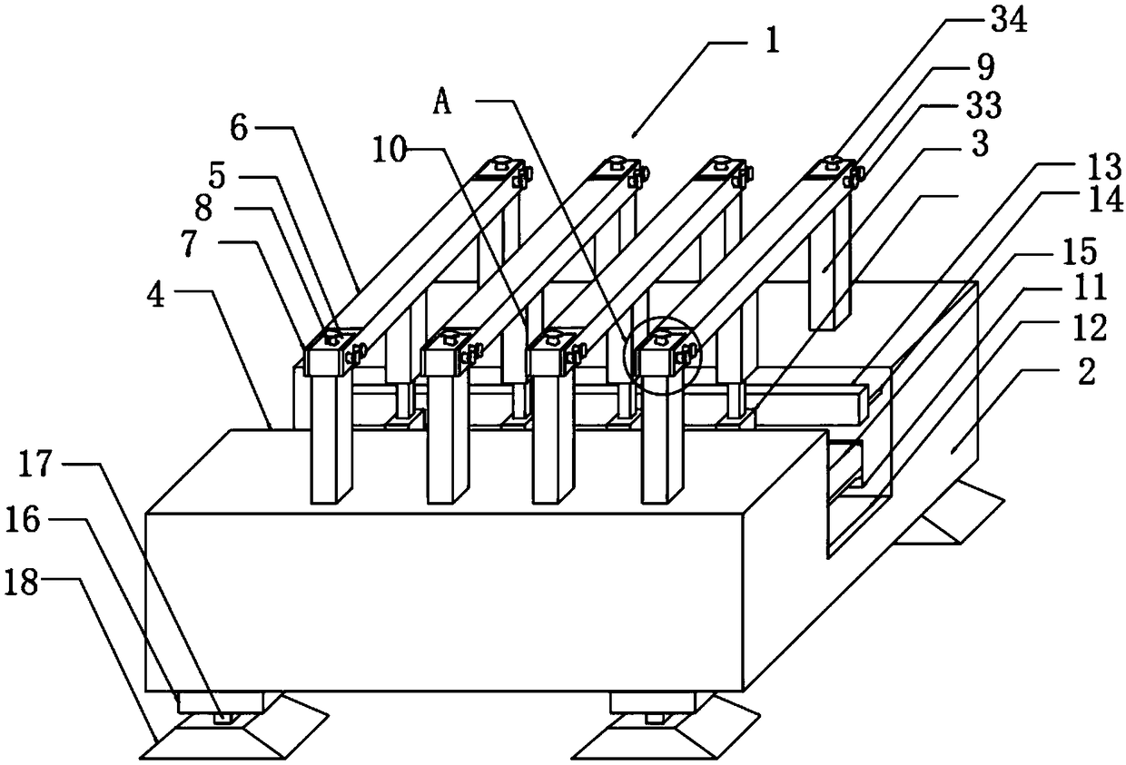
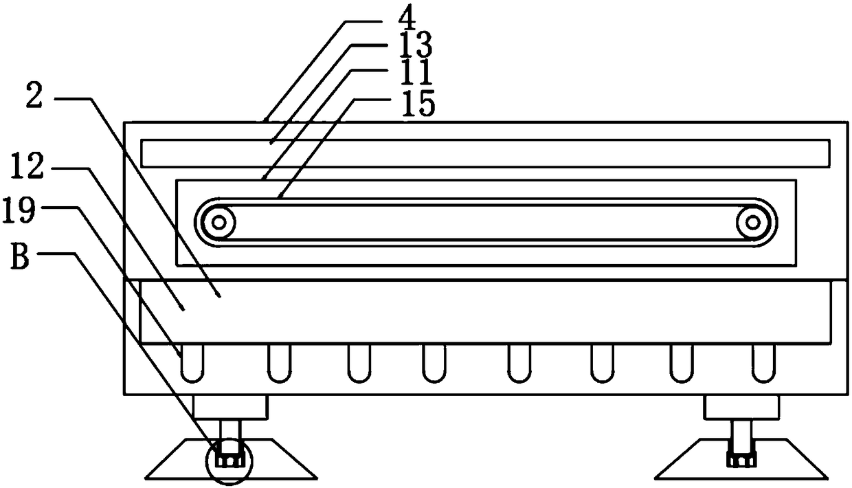
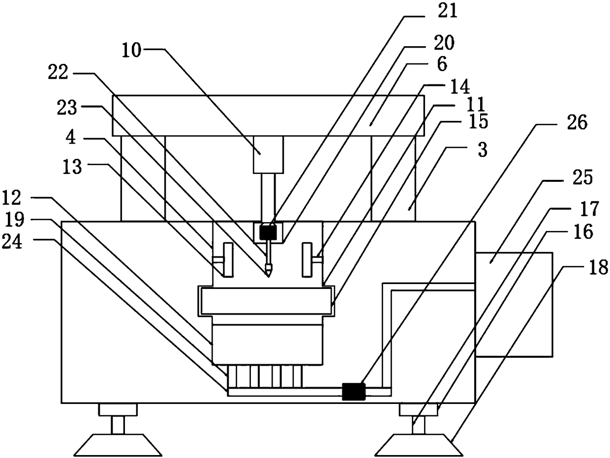
[0024] Such as Figure 1-5 As shown, a punching device for automatic fast punching includes a device body 1, and the device body 1 includes a support box 2 and a waste collection box 25, the support box 2 is located on one side of the waste collection box 25, and the support The top of the box 2 is provided with a first groove 4, and the top of the support box 2 is provided with a plurality of support rods 3, and a plurality of the support rods 3 are respectively located on both sides of the first groove 4, and a plurality of the support rods 3. First connection blocks 5 are provided on the top, and second connection blocks 6 are provided between the plurality of support rods 3, and second grooves 7 are provided at both ends of the plurality of second connection blocks 6, A plurality of the second grooves 7 are plugged with a plurality of first connecting blocks 5, the bottom of the second connecting block 6 is provided with a first hydraulic cylinder 10, and the hydraulic rod...


PUM


Abstract

The invention discloses a perforating device capable of achieving automatic and rapid perforating. The automatic perforating device comprises a device body; the device body comprises a support box anda waste collection box; a plurality of support rods are arranged at the top of the support box; the multiple support rods are located on the two sides of a first groove correspondingly; a plurality of first connecting blocks are arranged at the top of the multiple supporting rods; second connecting blocks are arranged between the multiple supporting rods; the two ends of the multiple second connecting blocks are provided with second grooves correspondingly; the multiple second grooves are connected with the first connecting blocks in an inserting mode; the bottoms of the second connecting blocks are provided with first hydraulic cylinders; the hydraulic rod ends of the first hydraulic cylinders are provided with motor boxes; the motor boxes are internally provided with motors; the outputends of the motors are provided with rotating shafts; the other ends of the rotating shafts are provided with drill bits; and the drill bits are located in the first groove. The perforating device iscompact in structure and convenient to use, by arranging the multiple drill bits, raw materials can be perforated more effectively and rapidly, the perforating speed is increased, the perforating efficiency is improved, the productivity is increased, and the production cost is reduced.

Description

technical field [0001] The invention relates to a punching device, in particular to a punching device for automatic fast punching, and belongs to the technical field of mechanical equipment. Background technique [0002] Punching machine refers to the general name of machinery and equipment that leaves cylindrical holes or holes on the target by means of rotary cutting or rotary extrusion with a tool that is harder and sharper than the target. The parts cooperate with each other to complete the punching process. First, move the material to the scanning area of ​​the camera of the automatic punching machine. After the camera scans the image, it will process it and send a signal to the control part. After the control part receives the signal, it will further process and control the action of the transmission part, so that the punch is X on the plane. Axis, Y axis move, the pneumatic part starts to work after the movement is completed, and the solenoid valve controls the cylin...

Claims


Application Information

Patent Timeline
IPC IPC(8): B23B39/16B23Q11/00
CPCB23B39/16B23Q11/0032B23Q11/0046
Inventor 黄钟葳
Owner 黄钟葳
Why Eureka
Try Eureka