Plate shearing machine with trimming device

A shearing machine and edge trimming technology, which is applied in the direction of shearing devices, machine tools suitable for grinding the edge of workpieces, and attachments of shearing machines, etc. It can solve the problems of affecting the use of workpieces, uneven shearing, time-consuming and laborious, etc. , to achieve the effect of improving trimming efficiency, ensuring cutting quality and ensuring stability

Pending Publication Date: 2019-01-11
NANTONG KANGHAI MACHINERY
View PDF0 Cites 6 Cited by
  • Summary
  • Abstract
  • Description
  • Claims
  • Application Information

AI Technical Summary

Problems solved by technology

[0002] The plate shearing machine is a machine that uses one blade to make a reciprocating linear motion relative to the other blade to cut the plate. It uses the moving upper blade and the fixed lower blade to apply shear to metal plates of various thicknesses with a reasonable blade gap. force, so that the plate is broken and separated according to the required size, but when the existing shearing machine cuts the workpiece, there will be unevenness or residual burrs at the shearing place, which will seriously affect the use of subsequent workpieces. Manual trimming is required, which is time-consuming and labor-intensive. For this reason, we propose a shearing machine with a trimming device

Method used


Image

  • Plate shearing machine with trimming device
  • Plate shearing machine with trimming device
  • Plate shearing machine with trimming device

Examples


Embodiment

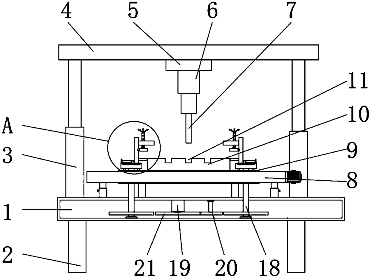
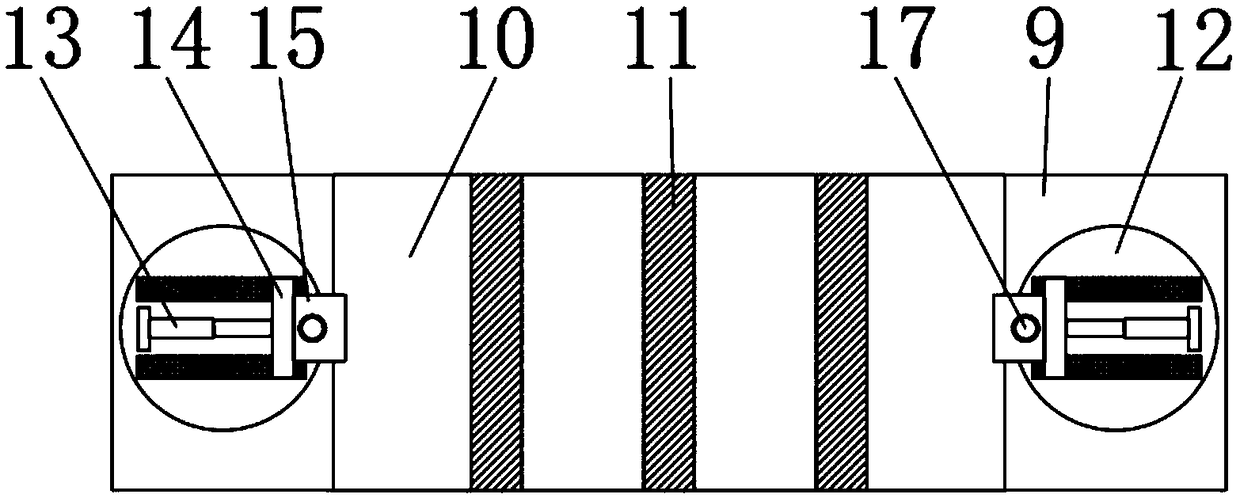
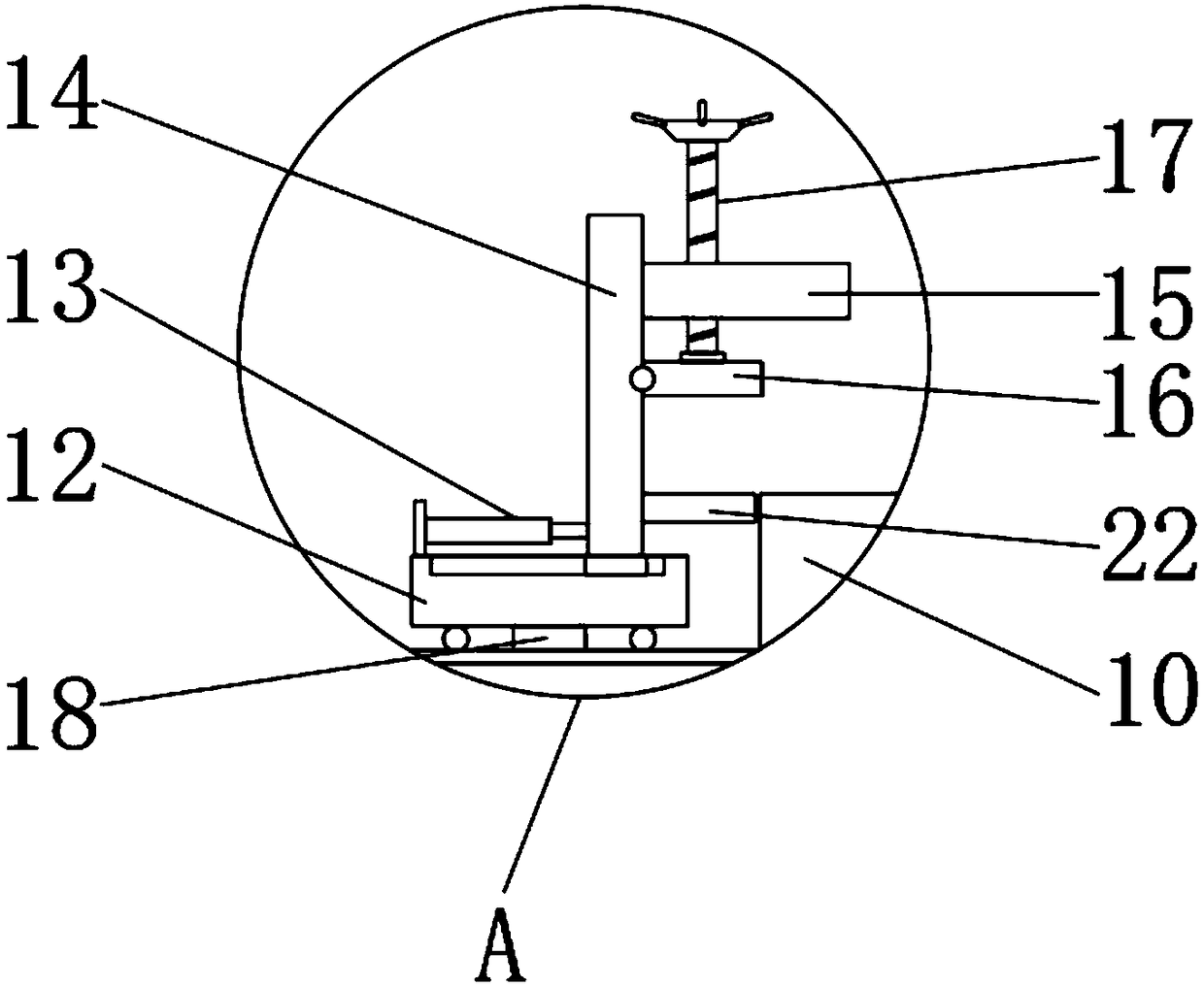
[0028] Embodiment: When in use, the plate workpiece is placed on the shear placement plate 10, and according to the length of the plate, start the electric telescopic rod 13 to shorten and extend to adjust the position of the support plate 10, so that the left and right sides of the bottom of the plate workpiece are located on the supporting plate 22 top, turn the screw rod 17 to drive the fixed plate 16 downward, fix the plate workpiece through the fixed plate 16 and the supporting plate 22, adjust the adjusting rod 81 to adjust the mounting block 82 to the designated position, and then move the moving block 5 and the moving guide rail 4. The upper blade 7 is adjusted to the position corresponding to the shear groove 11, and the hydraulic telescopic rod 3 is started to drive the moving guide rail 4 downward, so that the upper blade 7 cuts the plate workpiece downward. After the cutting is completed, the hydraulic telescopic rod 3 is started to drive Move the guide rail 4 upwar...


PUM


Abstract

The invention discloses a plate shearing machine with a trimming device in the technical field of plate shearing machines. The plate shearing machine comprises a base. An upper blade is arranged at the bottom of a buffering rod. A bearing plate is arranged above the top of the base. A shearing carrying plate is arranged on the top of the bearing plate. Shearing grooves matched with the upper bladeare evenly and longitudinally formed in the top of the shearing carrying plate. Rotating discs are arranged on the left side and the right side of the top of the bearing plate. A panel and a supporting plate are sequentially and fixedly arranged on the outer wall of the inner side of each supporting plate from top to bottom. A trimming device is arranged on the top of the base. After the plate shearing machine conducts plate shearing, a first servo motor is controlled to drive a drive gear to rotate so that the two sets of rotating discs can rotate forwards by 90 degrees from the interior, the sheared edge of a plate workpiece corresponds to a frosting disc, during trimming, a second servo motor drives a screw rod to rotate forwards and backwards, a movable block then moves left and rightin a transverse sliding groove, meanwhile, a drive motor drives the frosting disc to rotate and move left and right to conduct trimming, and the shearing quality of the plate workpiece is ensured.

Description

technical field [0001] The invention relates to the technical field of shearing machines, in particular to a shearing machine with an edge trimming device. Background technique [0002] The plate shearing machine is a machine that uses one blade to make a reciprocating linear motion relative to the other blade to cut the plate. It uses the moving upper blade and the fixed lower blade to apply shear to metal plates of various thicknesses with a reasonable blade gap. force, so that the plate is broken and separated according to the required size, but when the existing shearing machine cuts the workpiece, there will be unevenness or residual burrs at the shearing place, which will seriously affect the use of subsequent workpieces. Manual trimming is required, which is time-consuming and labor-intensive. For this reason, we propose a shearing machine with a trimming device. Contents of the invention [0003] The object of the present invention is to provide a shearing machine...

Claims


Application Information

Patent Timeline
Patent Type & Authority Applications(China)
IPC IPC(8): B23D15/06B23D33/02B24B9/04B23Q7/00B23Q11/00
CPCB23D15/06B23D33/02B23Q7/00B23Q11/0032B24B9/04
Inventor 康瀚艋
Owner NANTONG KANGHAI MACHINERY
Why Eureka
Try Eureka