
Axis aligned mechanism and assembling structure and assembling method for robot assembly

An assembly structure and robot technology, which is applied in the direction of assembly machines, metal processing, metal processing equipment, etc., can solve the problems of complex alignment process and inconvenient operation, and achieve the effect of simplifying the assembly structure

Active Publication Date: 2019-01-11
SUZHOU RS TECH
View PDF8 Cites 0 Cited by
  • Summary
  • Abstract
  • Description
  • Claims
  • Application Information

AI Technical Summary

Problems solved by technology

[0005] Therefore, the technical problem to be solved by the present invention lies in the defects that the shaft alignment process of the existing shaft alignment mechanism is complicated and inconvenient to operate

Method used


Image

  • Axis aligned mechanism and assembling structure and assembling method for robot assembly
  • Axis aligned mechanism and assembling structure and assembling method for robot assembly
  • Axis aligned mechanism and assembling structure and assembling method for robot assembly

Examples


Embodiment 1

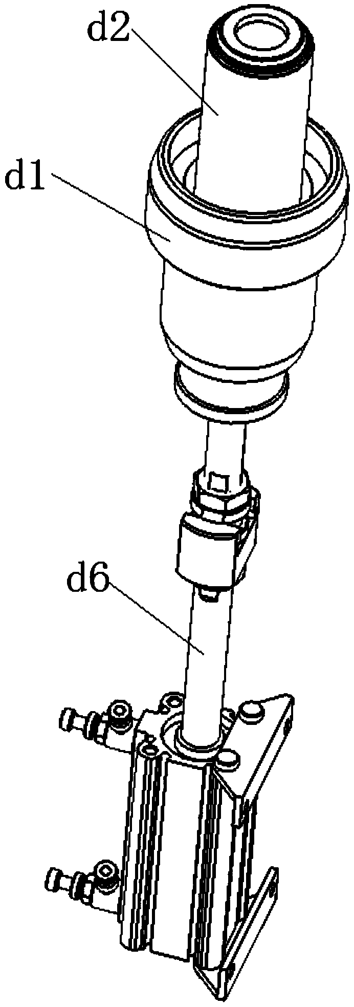
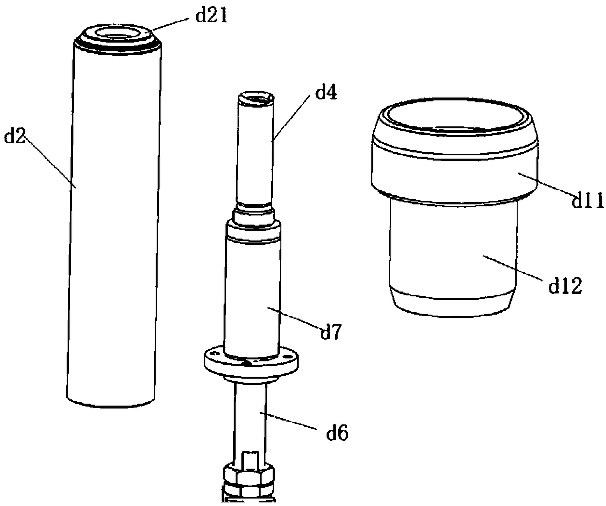
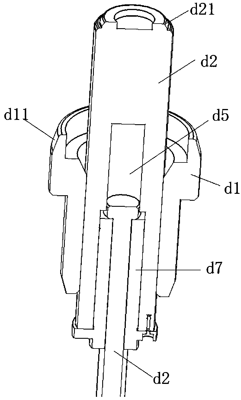
[0102] Embodiment 1 provides an alignment mechanism d, such as Figure 1 to Figure 4 As shown, it includes an annular support body d1 fixed relative to the frame and a shaft assembly coaxially and axially telescopically passing through the inner cavity of the annular support body d1. The annular support body d1 is sleeved by the inner hole of the first installation component, and the shaft assembly is sleeved by the inner hole of at least one second installation component.

[0103] For example, if Figure 5 and Figure 6 As shown, the first installation part can be the forearm casting a23 of the robot, and the second installation part is two, namely the wrist a22 and the synchronous wheel assembly of the reducer a211. The forearm casting a23, wrist a22 and The synchronous wheel assembly a211 of the reducer is taken as an example to describe the shaft alignment mechanism d in this embodiment in detail.

[0104] Such as Figure 4 As shown, there is a workbench f1 on the fram...

Embodiment 2

[0122] This embodiment provides an assembly structure of robot components, such as Figure 7 to Figure 11 As shown, the assembly structure includes the f1 workbench set on the frame, the shaft alignment mechanism d in embodiment 1, the positioning mechanism f, the pressing mechanism e, the manipulator, the adjustment mechanism c, and the limit mechanism b.

[0123] Such as Figure 7 to Figure 11As shown, there is also a support platform j1 on the frame, and a first installation frame j2, a second installation frame j3, and a third installation frame j4 are also provided on the support platform j1, which are respectively used to place the forearm casting a23 and the wrist a22 And reducer synchronous wheel assembly a211, in the initial state, the forearm casting a23, wrist a22 and reducer synchronous wheel assembly a211 are respectively arranged on the respective mounting frames on the support platform j1. The workbench f1 is set on the top of the support platform j1, the top s...


PUM


Abstract

The invention discloses an axis aligned mechanism and an assembling structure and an assembling method for a robot assembly. The axis aligned mechanism comprises an annular supporting body and a shaftassembly, wherein the annular supporting body is fixed relative to a machine frame and is used for arranging an inner hole of a first mounting part in a sleeve mode; and the shaft assembly is coaxially and axially telescopically arranged in the inner cavity of the annular supporting body in a penetrating mode, and is used for arranging inner holes of at least one second mounting part in a sleevemode. The assembling structure comprises the axis aligned mechanism, and the assembling method adopts the assembling structure. When the inner hole of the first mounting part and the inner holes of the second mounting parts are correspondingly arranged outside the annular supporting body and the shaft assembly in a sleeve mode, the axis of the inner hole of the first mounting part can be aligned with the axes of the inner holes of the second mounting parts, so that the operation of the axis aligned mechanism is simplified, and the assembling efficiency of the mounting parts can be improved; and the shaft assembly can extend and contract in the axial direction, so that when the second mounting parts are assembled on the first mounting part, the concession room can be realized, and thereforethe plurality of second mounting parts can be conveniently installed on the first mounting part from different angles.

Description

technical field [0001] The invention relates to the technical field of robot assembly, in particular to a shaft alignment mechanism, an assembly structure and an assembly method of robot components. Background technique [0002] At present, in the assembly process of the robot's forearm casting, wrist and reducer synchronous wheel assembly, it is necessary to adjust the inner hole of the forearm casting, the inner hole of the wrist and the inner hole of the reducer synchronous wheel assembly. The axes are aligned so that the wrist and reducer synchronous wheel assembly fits accurately on the arm casting. [0003] In the prior art, when installing the forearm casting, wrist and reducer synchronous wheel assembly, simply place the forearm casting on the workbench, and directly install the wrist and reducer synchronous wheel assembly on the forearm casting , and then take a photo to detect whether the axis of the wrist and the synchronous wheel assembly of the reducer is align...

Claims


Application Information

Patent Timeline
Patent Type & Authority Applications(China)
IPC IPC(8): B23P21/00B23P19/00B23P19/02
CPCB23P19/00B23P19/02B23P21/00
Inventor 吴加富缪磊许新星冯小平
Owner SUZHOU RS TECH
Learn More