Kinematics calibration method and system for flexible robot

A technology of robot kinematics and calibration method, which is applied in the field of flexible robot kinematics calibration method and system, can solve problems affecting joint angle, error, end error, etc., and achieve the effect of improving calibration accuracy

Active Publication Date: 2019-01-11
HARBIN INST OF TECH SHENZHEN GRADUATE SCHOOL
View PDF9 Cites 12 Cited by
  • Summary
  • Abstract
  • Description
  • Claims
  • Application Information

AI Technical Summary

Problems solved by technology

These errors are accumulated and amplified by multiple joints, which eventually lead to large errors at the end
[0004] (2) The limited space at the joints and the special rope driving method lead to the fact that the sensors are mainly concentrated at the root of the robot, and cannot directly feed back the angle of the joints, and there is an error in the joint angles
[0005] (3) The driving rope has a certain degree of elasticity. After repeated use, the driving rope of the flexible robot will become longer, which in turn will affect the angle of the joint, resulting in an error at the end
However, since the rope-driven flexible robot belongs to the series-parallel robot, its kinematic parameters are numerous and the parameters show a strong coupling effect on each other, resulting in the inconsistency between the kinematic parameter error of each kinematics and the position and attitude error of the end. Linear relationship, traditional model-based calibration methods are difficult to apply directly

Method used


Image

  • Kinematics calibration method and system for flexible robot
  • Kinematics calibration method and system for flexible robot
  • Kinematics calibration method and system for flexible robot

Examples


Embodiment 1

[0054] A method for calibrating the kinematics of a flexible robot, comprising a linkage joint segment calibration step and a robot calibration step, wherein the linkage joint segment calibration step includes:

[0055] According to the nominal joint angle of the linkage joint segment (ie, the theoretical joint angle), the nominal pose (ie, the theoretical pose) of the linkage joint segment under zero linkage angle error is obtained. In the present invention, the terminal position and posture are referred to as pose.

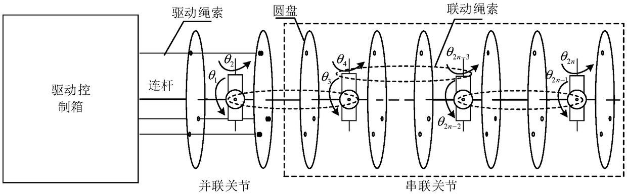
[0056] Use the parameter decoupling driving structure to drive the linkage joint segment so that the driving rope reaches the nominal length of the linkage joint segment (that is, the theoretical length of the rope), and obtain the actual pose of the linkage joint segment, where the calculation is based on the nominal joint angle of the linkage joint segment Get the nominal rope length of the linkage joint segment, refer to figure 2 , figure 2 It is a schemat...

Embodiment 1

[0064] Obtain embodiment 2 based on embodiment 1, the robot calibration step also includes:

[0065] Obtain the nominal pose of the robot under the linkage angle error of the robot according to the nominal joint angle of the robot;

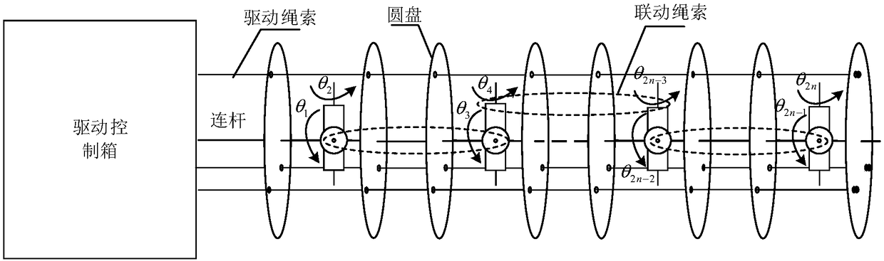
[0066] refer to figure 1 , use the normal driving structure to drive the robot so that the driving rope reaches the nominal rope length of the robot, and obtain the actual pose of the robot, calculate the nominal rope length of the robot according to the nominal joint angle of the robot, and use different normal drive for different linkage joint segments Structural drive, each linkage joint segment is driven by a normal drive structure. In this embodiment, the normal driving structure uses three driving ropes to drive the linkage joint segment, and is provided with a motor position sensor and a rope tension sensor. When driving the whole arm of the robot, among the three motors of the three driving ropes in each linkage joint segment, one motor ...

Embodiment 3

[0070] Embodiment 3 is a concrete description of the specific implementation process of the flexible robot kinematics calibration method:

[0071] First, the kinematics analysis of the rope-driven manipulator is carried out. The kinematics analysis of the rope-driven super-redundant manipulator includes not only the mapping relationship between the joint space and the operation space, but also the mapping relationship between the rope driving space and the joint space. Therefore, its kinematic analysis can be divided into two steps: first, deduce the mapping relationship between the joint space and the operation space, that is, the relationship between the pose of the robot end coordinate system and the joint variables ψ, α; then deduce the mapping between the rope drive space and the joint space The relationship, that is, the relationship between the joint variables ψ, α and the change in the length of the driving rope Δli, such as Figure 4 shown.

[0072] First, the mappin...


PUM


Abstract

The invention discloses a kinematics calibration method and system for a flexible robot. The method comprises: obtaining the nominal position and posture of a linkage joint segment under zero linkageangle error according to the nominal joint angle of the linkage joint segment; driving the linkage joint segment to reach the nominal rope length of the linkage joint segment by using a parameter decoupling driving structure, obtaining the actual position and posture of the linkage joint segment, finally, obtaining the linkage angle error of the linkage joint segment according to the nominal position and posture of the linkage joint segment and the actual position and posture of the linkage joint segment; and obtaining the linkage angle error of the robot according to the linkage angle errorsof multiple linkage joint segments. The technical problem that the kinematics error parameters of the existing wire drive flexible robot are numerous, strong coupling between the parameters due to theseries-parallel structure, and the parameter calibration precision is low are overcome, and the calibration precision of the robot is improved.

Description

technical field [0001] The invention relates to the field of robots, in particular to a kinematics calibration method and system for a flexible robot. Background technique [0002] At present, the existing flexible robot with 2m degree of freedom is composed of m joint segments connected in series, and each joint segment is driven by more than 3 ropes, with motor position sensors and rope tension sensors. refer to figure 1 , figure 1 is a schematic diagram of a joint segment of an existing flexible robot; figure 1 In , the driving connection of a linkage joint segment is illustrated. The joint segment is driven by three driving cables, and the sub-joints of the joint segment form a series-parallel structure through the driving rope and the linkage cable. Compared with traditional manipulators, soft robots have a slender torso and redundant degrees of freedom. They show strong flexibility in complex and multi-obstacle environments. Therefore, they are widely used in the ma...

Claims


Application Information

Patent Timeline
Patent Type & Authority Applications(China)
IPC IPC(8): B25J9/06B25J9/10B25J9/16B25J17/00B25J19/00
CPCB25J9/06B25J9/1045B25J9/1635B25J17/00B25J19/00
Inventor 徐文福刘天亮牟宗高梁斌
Owner HARBIN INST OF TECH SHENZHEN GRADUATE SCHOOL
Why Eureka
Try Eureka