
Automatic rotor cutting machine

A cutting machine and cutting mechanism technology, which can be applied to household appliances, other household appliances, household components, etc., can solve the problems of automatic feeding and unloading, and achieve high practical value, reliable clamping, and reduce complexity. Effect

Pending Publication Date: 2019-01-11
浙江三信智能机械股份有限公司
View PDF1 Cites 0 Cited by
  • Summary
  • Abstract
  • Description
  • Claims
  • Application Information

AI Technical Summary

Problems solved by technology

However, this patent only realizes the automation of cutting operations, and does not involve automatic loading and unloading

Method used


Image

  • Automatic rotor cutting machine
  • Automatic rotor cutting machine
  • Automatic rotor cutting machine

Examples


Embodiment

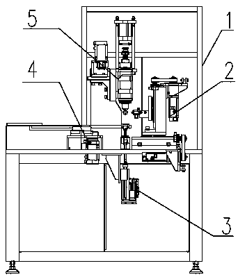
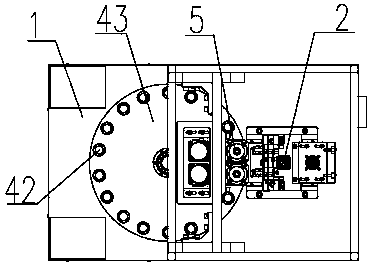
[0028] Such as figure 1 and figure 2 As shown, an automatic rotor cutting machine includes a frame 1, and the frame 1 is provided with a feeding mechanism 4 and a feeding mechanism 3;

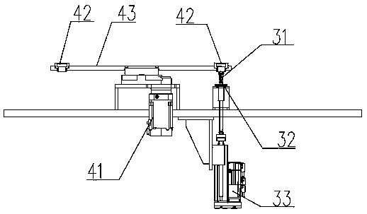
[0029] Such as image 3 As shown, the feed mechanism 4 includes a feed tray 43 horizontally arranged on the frame 1, and a rotary drive unit 41 that drives the feed tray 43 to rotate around the vertical direction. A number of feed holes 42 vertically penetrating the feed tray 43 are distributed.

[0030] Such as image 3 As shown, the feeding mechanism 3 includes two jacking heads 31 located below the tray 43, and the feeding mechanism 3 also includes a lifting drive unit 33 that drives the jacking heads 31 to pass through the corresponding material holes 42; The lifting head 31 is provided with a length adjusting device 32, which adjusts the length of the lifting head 31 to improve the accuracy of feeding.

[0031] Such as figure 1 As shown, it also includes a clamping mechanism 5 arran...


PUM


Abstract

The invention relates to automatic equipment, and in particular, discloses an automatic rotor cutting machine. The automatic rotor cutting machine comprises a frame; a feeding mechanism and a supply mechanism are arranged on the frame; the feeding mechanism comprises a tray horizontally arranged on the frame, and a rotary driving unit for driving the tray to rotate in the vertical direction; multiple holes penetrating through the tray in the vertical direction are annularly distributed on the tray around a rotating center; the supply mechanism comprises at least one ejecting head positioned under the tray; and the supply mechanism further comprises a lifting driving unit for driving the ejecting heads to penetrate through the corresponding holes. The automatic rotor cutting machine furthercomprises clamping mechanisms arranged above the tray and corresponding to the ejecting heads one to one, and cutting mechanisms positioned on sides of the clamping mechanisms. Through cooperative work of the feeding mechanism and the supply mechanism, the automatic rotor cutting machine realizes automatic loading and unloading.

Description

technical field [0001] The invention relates to an automatic equipment, in particular to an automatic rotor cutting machine. Background technique [0002] Smaller rotors are often produced by injection molding, and the injection molding process will inevitably leave burrs on the surface of the rotor. In order to ensure the performance of the rotor, it is necessary to remove the burrs. The burr can be manually removed, or a cutting device can be used to cut the burr-prone parts of the rotor. [0003] The Chinese utility model patent with the authorized announcement number CN204835856U discloses a motor rotor cutting machine, including a fixture base, a fixture, a cutting tool, a transverse guide rail, a longitudinal guide rail, a transverse feed mechanism and a longitudinal feed mechanism. High, good cutting effect, the servo motor and the cylinder are connected with a control system, the control is more convenient, not easy to make mistakes, the whole process is unmanned op...

Claims


Application Information

Patent Timeline
Patent Type & Authority Applications(China)
IPC IPC(8): B29C37/02
CPCB29C37/02B29L2031/7498
Inventor 严滔滔
Owner 浙江三信智能机械股份有限公司
Learn More