Pressure vessel system

A pressure vessel and integrated technology, applied in the field of biomass pretreatment equipment, can solve the problems of occupying the discharge port and continuing to use the hopper

Inactive Publication Date: 2019-01-11
高建鑫
View PDF8 Cites 0 Cited by
  • Summary
  • Abstract
  • Description
  • Claims
  • Application Information

AI Technical Summary

Problems solved by technology

[0003] The discharge valve in the pressure vessel system is different from the traditional valve in structure, and it occupies the space above and below the discharge port at the same time. Obviously, the traditional hopper cannot continue to be used in such an environment. See reports on technical solutions related to

Method used


Image

  • Pressure vessel system
  • Pressure vessel system

Examples


Embodiment Construction

[0021] The present invention will be further described below in conjunction with specific examples, without limiting the present invention.

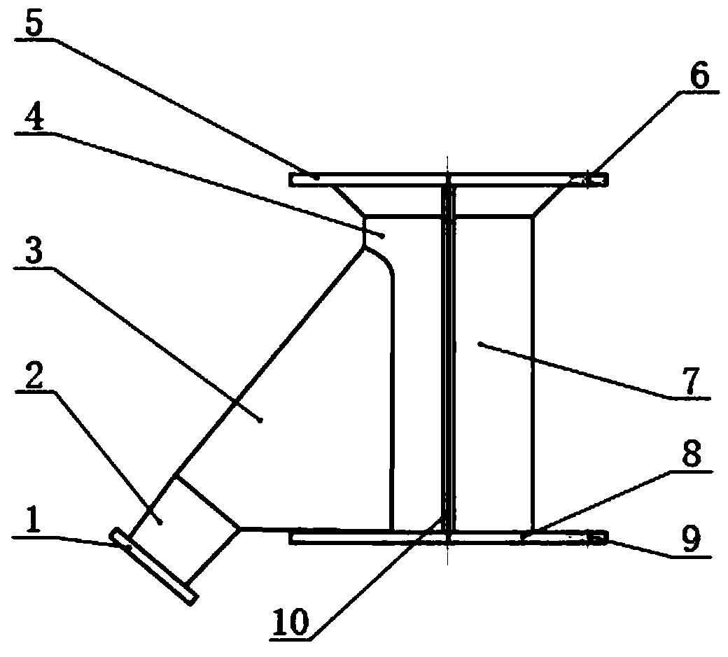
[0022] Firstly, drill blind holes and tap on the corresponding positions of the upper support cover and the lower flange of the discharge valve, each with a circle of ¢6mm screw holes.

[0023] The hopper parts made according to the design requirements are sent to the corresponding position from the large gap between the valve pillars on both sides, equipped with metal gaskets, and fastened with ¢6mm bolts until completely sealed and leak-free.

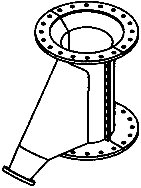
[0024] The special-shaped three-way hopper has one connection to the discharge port, one connection to the sealing block, and one connection to guide the spraying and blasting material, which is completely suitable for the special situation that the discharge valve is different.

[0025] When the pressure vessel system is sprayed, the sealing block descends rapidly, and the steam entrains the ma...


PUM


Abstract

Provided is a special-shaped guide hopper suitable for a novel pressure vessel system. A collection barrel is installed on the inner side of a pillar of a novel blow-off valve and communicated with alateral guide cover, and then a special-shaped device which can meet special requirements of the novel blow-off valve and has collection and guide functions is formed. The whole structure is simple and practical. The material passing rate is high. There are fewer residues in the hopper, and no material accumulates in the hopper.

Description

technical field [0001] The invention relates to biomass pretreatment equipment, and aims at a pressure vessel system, which is a special-shaped device for collecting and transporting materials. Background technique [0002] Steam explosion is a high-temperature and high-pressure treatment of biomass materials using a pressure vessel. When it is sprayed, the material gushes out from the discharge valve in an instant, and scatteres around in the form of agglomerates. It is necessary to use a hopper to collect and transport materials. A variety of hoppers guide materials along the bottom of the discharge valve, and the effect is obvious. [0003] The discharge valve in the pressure vessel system is different from the traditional valve in structure, and it occupies the space above and below the discharge port at the same time. Obviously, the traditional hopper cannot continue to be used in such an environment. See the report of the technical solution related to it. Contents o...

Claims


Application Information

Patent Timeline
Patent Type & Authority Applications(China)
IPC IPC(8): D21B1/36
Inventor 不公告发明人
Owner 高建鑫
Why Eureka
Try Eureka