Simple gear transmission timing alignment mechanism and operation method thereof

A timing mechanism and operation method technology, applied in mechanical equipment, engine components, machines/engines, etc., can solve problems such as difficulty in not rotating the timing gear, problems in the timing mechanism, low assembly efficiency, etc., to eliminate the valve Topping and fuel pump timing errors, improved assemblability, ease of assembly effect

Inactive Publication Date: 2019-01-11
GUANGXI YUCHAI MASCH CO LTD
View PDF7 Cites 0 Cited by
  • Summary
  • Abstract
  • Description
  • Claims
  • Application Information

AI Technical Summary

Problems solved by technology

Since the engine has crankshaft timing gears, idler gears, fuel injection pump gears, camshaft gears and other gears that need to be aligned, the entire assembly process is a relatively long assembly process, and it is difficult to keep the timing gears from rotating during the assembly process. It is not easy to be found after the engine rotates, and the assembly efficiency is low
like figure 1 As shown, there are timing marks on gear a 3, gear b 4, and gear c 5. During assembly, gear b 4 needs to be matched with the timing marks on gear a 3 and gear c 5, that is, gear a 3 Timing mark 6 and b gear 4 timing mark 7 need to be paired, and b gear 4 timing mark 8 and c gear 5 timing mark 9 also need to be paired, if after completing the assembly of a gear 3 and b gear 4, The gears are easy to rotate relative to each other. When c-gear 5 is paired with the marks on b-gear 4, there will be problems with the timing mechanism driven by c-gear 5, resulting in corresponding failures

Method used


Image

  • Simple gear transmission timing alignment mechanism and operation method thereof
  • Simple gear transmission timing alignment mechanism and operation method thereof
  • Simple gear transmission timing alignment mechanism and operation method thereof

Examples


Embodiment Construction

[0021] The specific embodiments of the present invention will be described in detail below in conjunction with the accompanying drawings, but it should be understood that the protection scope of the present invention is not limited by the specific embodiments.

[0022] Unless expressly stated otherwise, throughout the specification and claims, the term "comprise" or variations thereof such as "includes" or "includes" and the like will be understood to include the stated elements or constituents, and not Other elements or other components are not excluded.

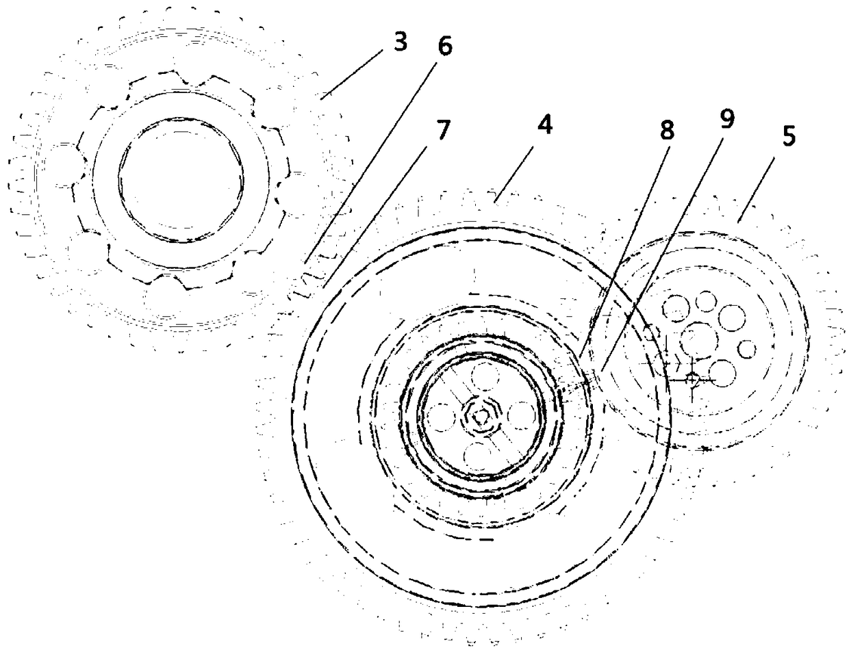
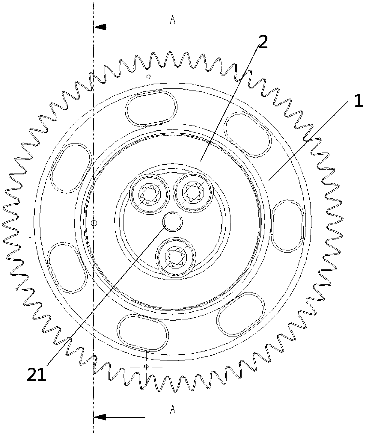
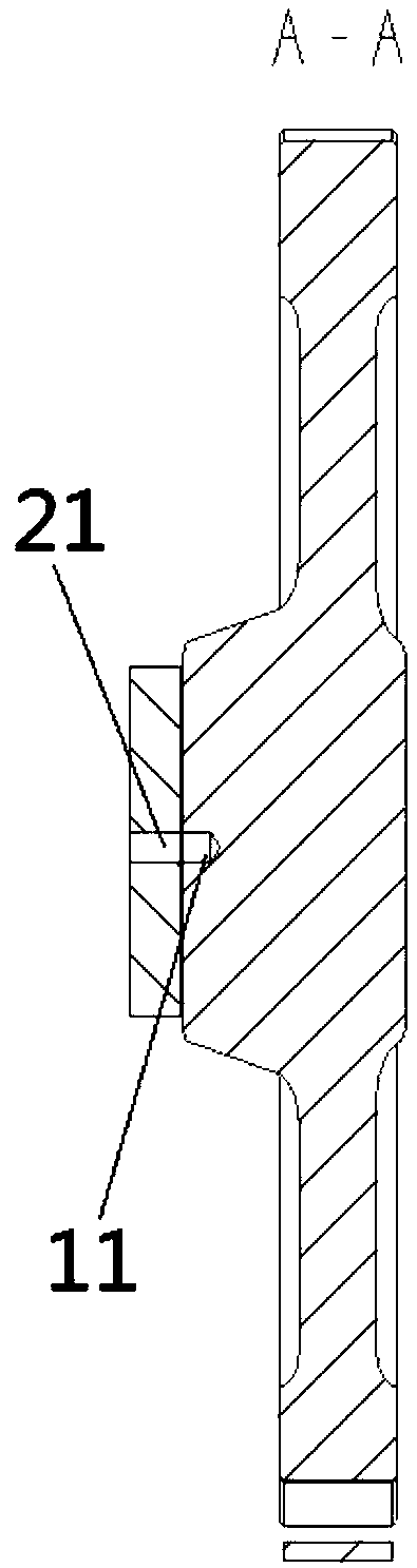
[0023] Such as Figure 2 to Figure 3 As shown, the simple gear transmission pair timing mechanism according to the preferred embodiment of the present invention is used to assemble the timing gear train. The simple gear transmission pair timing mechanism at least includes: an idler gear 1, an anti-friction surface or an anti-friction surface on the idler gear shaft 2 A first positioning through hole 21 is opened on the pla...


PUM


Abstract

The invention discloses a simple gear transmission timing alignment mechanism and an operation method thereof. The simple gear transmission timing alignment mechanism is used for assembling a timing gear system, and the simple gear transmission timing alignment mechanism at least comprises an idle gear, a first positioning through hole is formed in an anti-attrition face or anti-attrition plate onan idle gear shaft, a first blind hole is formed on the corresponding timing position of the idle gear, when the idle gear is aligned with a crankshaft timing gear or a first gear which is assembledfirstly, the first positioning through hole can correspond to the position of the first blind hole, a first positioning mechanism, the first positioning through hole and the first blind hole are positioned, and the idle gear is fixed. Through the simple gear transmission timing alignment mechanism, engine assembling ability can be greatly improved, timing gear assembling accuracy is improved, relative rotation happening after wrong assembly and assembly of the timing gear can be effectively prevented, and the wrong assembly of subsequent timing gears can be avoided.

Description

technical field [0001] The invention relates to the field of internal combustion engines, in particular to a simple gear transmission pair timing mechanism and an operation method thereof. Background technique [0002] The gear train of the traditional gear drive timing system needs to be marked according to the timing marks on the gears when installing or maintaining the engine. Only when the marks are correct can the engine run normally. Serious failures such as broken pistons and rocker arms. And in the process of engine assembly and alignment, the crankshaft cannot rotate, because the phenomenon of a wrong tooth is prone to occur in the case of a small rotation angle of the crankshaft, if it rotates, it may cause the wrong tooth and produce the above-mentioned failure. There is also the possibility of misalignment due to misuse causing the crankshaft to turn. [0003] Specifically, the traditional timing system of gears generally adopts mark-to-point assembly. Generall...

Claims


Application Information

Patent Timeline
Patent Type & Authority Applications(China)
IPC IPC(8): F01L1/352F01L1/344
CPCF01L1/344F01L1/352
Inventor 向本杰余锦海王鹏程覃文王志刚黎华文田战胜张通
Owner GUANGXI YUCHAI MASCH CO LTD
Why Eureka
Try Eureka