Engine cooling system, box used for engine cooling system and operation machine

A technology for engine cooling and engine cylinders, applied in the direction of engine cooling, engine components, machines/engines, etc., can solve the problems of pump water supply capacity damage to the cooling system, heat exchange performance reduction, thermal stress impact, etc., to slow down flow, Reduce impact and realize the effect of heat exchange

Active Publication Date: 2019-01-11
CATEPILLAR SARL
View PDF5 Cites 4 Cited by
  • Summary
  • Abstract
  • Description
  • Claims
  • Application Information

AI Technical Summary

Problems solved by technology

These air bubbles are mixed in the coolant, which will cause thermal stress impact on the cooling tube of the heat exchanger, resulting in a decrease in heat exchange performance
At the same time, these bubbles will cause a partial vacuum in the engine cooling system, which will damage the water supply capacity of the pump of the cooling system, so that the heat generated by the engine during work cannot be taken away by the coolant in time and become overheated.

Method used


Image

  • Engine cooling system, box used for engine cooling system and operation machine
  • Engine cooling system, box used for engine cooling system and operation machine
  • Engine cooling system, box used for engine cooling system and operation machine

Examples


Embodiment Construction

[0024] The technical solutions of the present invention will be further specifically described below through the embodiments and in conjunction with the accompanying drawings. The following description of the embodiments of the present invention with reference to the accompanying drawings is intended to explain the general inventive concept of the present invention, but should not be construed as a limitation of the present invention.

[0025] Additionally, in the following detailed description, for purposes of explanation, numerous specific details are set forth in order to provide a thorough understanding of the disclosed embodiments. It may be evident, however, that one or more embodiments may be practiced without these specific details. In other instances, well-known structures and devices are shown in diagrammatic form to simplify the drawings.

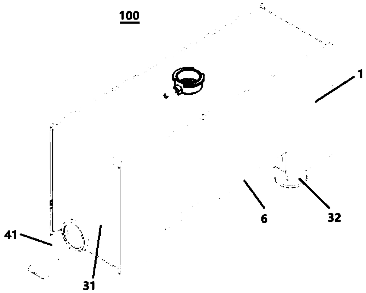
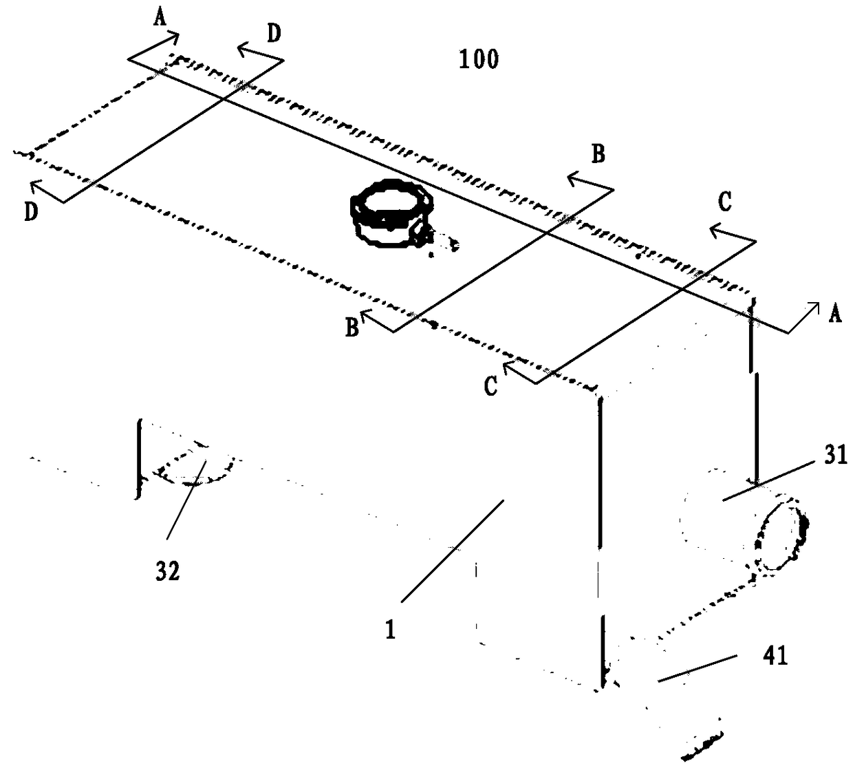
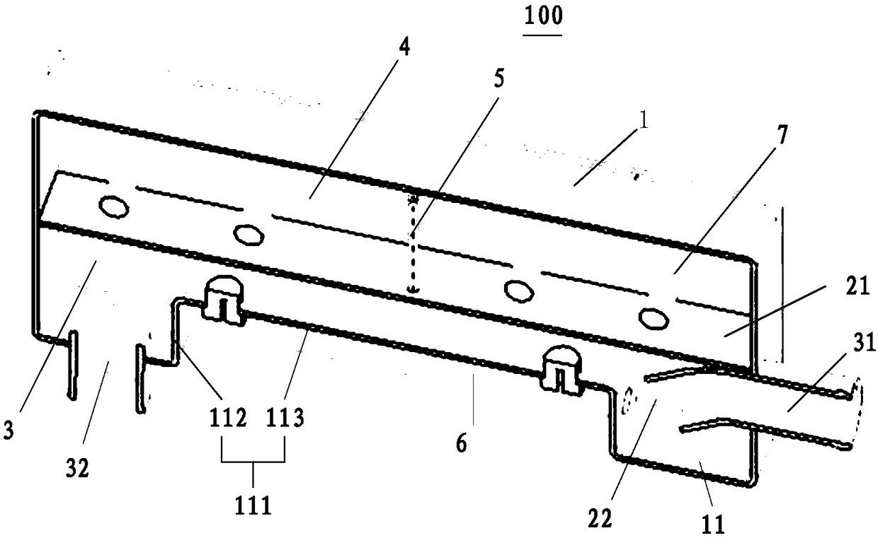
[0026] Figure 11 A schematic diagram of an exemplary engine cooling system is shown. The engine cooling system realizes the...


PUM


Abstract

The invention relates to an engine cooling system, a box used for the engine cooling system and an operation machine. The box includes a housing and a partition, and the partition separates the housing into an exhaust box and an expansion tank which are sealed relative to each other. The exhaust box includes a first connecting pipe and a second connecting pipe, the first connecting pipe is suitable for being in fluid connection to an engine cylinder sleeve of the engine cooling system to introduce cooling liquid into the exhaust box, and the second connecting pipe is suitable for being in fluid connection with a heat exchanger of the engine cooling system to discharge the cooling liquid into the heat exchanger. The expansion tank includes a third connecting tube suitable for being in fluidconnection into the engine cooling system. The box further includes an air guiding tube, the first end of the air guiding tube is in communication with the exhaust box, and the second end of the airguiding tube is arranged in the expansion box, so that gas contained in the cooling liquid flowing through the exhaust box is exported into the expansion tank through the air guiding tube. The exhaustbox enables the gas in the cooling liquid to be pre-separated before entering the heat exchanger, and the thermal stress shock to the heat exchanger is reduced.

Description

technical field [0001] The present invention relates to a box body used in an engine cooling system, and also relates to an engine cooling system and an operating machine including the box body. Background technique [0002] Working machinery uses engine cooling system to prevent the engine from overheating, which is particularly important in heavy machinery (such as loaders) with high engine compression ratio and high heat generation. [0003] The engine cooling system uses a coolant pump to drive the flow of coolant through the cooling system. An engine cylinder liner is arranged outside the engine block, and the coolant flows through the engine cylinder liner under the action of the coolant pump to take away the heat generated by the engine during operation, and then the high-temperature coolant enters the heat exchanger to cool the coolant Cooling is carried out, and the cooled coolant enters the engine cylinder liner again through the coolant pump to realize the circul...

Claims


Application Information

Patent Timeline
Patent Type & Authority Applications(China)
IPC IPC(8): F01P11/02
CPCF01P11/028F01P11/029F01P5/10F01P11/04F02F1/16
Inventor 董礼田国平刘更新徐克生
Owner CATEPILLAR SARL
Why Eureka
Try Eureka