Shock absorbing method and structure of spherical hinge for wheelless axle bogie

A technology of bogies and ball joints, which is applied in the field of rail transit, can solve problems such as vehicles that cannot be applied to bogies without axles, and achieve the effects of reducing rubber stress, improving anti-fatigue life, and increasing service life

Active Publication Date: 2019-01-11
ZHUZHOU TIMES RUIWEI ANTI VIBERATION EQUIP LTD
View PDF4 Cites 2 Cited by
  • Summary
  • Abstract
  • Description
  • Claims
  • Application Information

AI Technical Summary

Problems solved by technology

However, this structure and performance cannot be applied to models without axle bogies

Method used


Image

  • Shock absorbing method and structure of spherical hinge for wheelless axle bogie
  • Shock absorbing method and structure of spherical hinge for wheelless axle bogie
  • Shock absorbing method and structure of spherical hinge for wheelless axle bogie

Examples


Embodiment 1

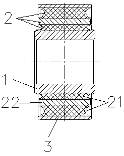
[0030] Such as figure 1 and figure 2 As shown, this embodiment is the best embodiment of the present invention, a structure of a ball joint for a wheelless bogie, which is an inner metal inner sleeve 1, a split-type composite layer structure 2 in the middle, and an outer metal inner sleeve. The jacket 3, wherein the composite layer structure 2 is a rubber-metal-rubber structure formed by setting a metal separator 22 inside the rubber layer 21 and vulcanizing the rubber layer 21, and the composite layer structure 2 is vulcanized and bonded to the metal inner sleeve 1 and the metal outer sleeve 3 between. The split composite layer structure 2 used can not only ensure that the precompression can be transferred from the outer rubber to the inner rubber when the ball joint is formed, but also reduce the deflection stiffness and torsional stiffness of the ball joint. Axial stiffness has very little effect. The parting surface at the parting position enables the rubber layer 21 t...

Embodiment 2

[0038] In this embodiment, the metal inner sleeve 1 and the composite layer structure 2 are vulcanized and bonded, and the composite layer structure 2 and the metal jacket 3 are assembled by interference. By setting the interference amount between the composite layer structure 2 and the metal jacket 3 Controls the amount of pre-compression of the rubber layer.

Embodiment 3

[0040] In this embodiment, the composite layer structure 2 can be divided into four lobes or more. When the composite layer structure 2 is divided into four lobes, the two lobes can be vulcanized symmetrically on the outside of the metal inner sleeve 1 first, and then pressed into the metal outer sheath 3 together with the other two lobes, so that a smaller diameter axis can be achieved Stiffness ratio; In addition, this method can also be used to realize that the assembled two petals are a hollow structure, and the vulcanized two petals are a solid structure, so that the radial space and solid functions can be realized.

[0041] At the same time, when there are more petals, the difficulty of design and processing will increase accordingly.

[0042] It can be seen from the above embodiments that the present invention also relates to a shock absorbing method for a ball joint used in a wheel-axle bogie, which adopts the method of setting a split composite layer structure 2 betwe...


PUM


Abstract

The invention relates to a shock absorbing method and structure of a spherical hinge for a wheelless axle bogie, which adopt the method of arranging a split composite layer structure between a metal inner sleeve and a metal outer sleeve to meet the performance requirements of the spherical hinge, wherein the composite layer structure is that a metal separator plate is arranged inside a rubber layer and is vulcanized to form a rubber-metal-rubber structure, and a parting surface is arranged at the splitting position of the composite layer structure to meet the radial, axial, deflection and torsional stiffness requirements, and reduce rubber stress. As the split composite lay structure is arranged between the metal inner sleeve and the metal outer sleeve, the invention can realize large radial pre-compression to rubber, improve radial rigidity of the spherical hinge and realize minimal torsional rigidity. The invention has the characteristics that the free surface of rubber is greatly increased by the parting surface arranged at the splitting position, which can greatly reduce the stress caused by the extrusion to rubber, improve the fatigue life of rubber and the service life of thespherical hinge.

Description

technical field [0001] The invention relates to a damping method and structure of a ball joint, in particular to a damping method and structure of a ball joint for a wheel-axle bogie, and belongs to the technical field of rail transportation. Background technique [0002] The axleless bogie is a completely different technology from traditional bogies such as BT, AT and domestic models. The speed of the vehicle covers 160 km-350 km per hour. The biggest feature of this axleless bogie is: the same bogie The two wheels can pass through the track curve at a differential speed, reducing wheel rim wear, and the vehicle is more stable when passing the curve, but at the same time, the various load conditions of the metal rubber parts are more severe. It has high technical requirements for various spherical joints, and products of the same structure need to be used in different positions. Therefore, the requirements for the bearing capacity of the product in all directions are high, ...

Claims


Application Information

Patent Timeline
Patent Type & Authority Applications(China)
IPC IPC(8): F16C11/06F16F15/08
CPCF16C11/0638F16F15/08
Inventor 陈俊辉黄江彪张玉祥罗俊蒋仲三曾先会
Owner ZHUZHOU TIMES RUIWEI ANTI VIBERATION EQUIP LTD
Why Eureka
Try Eureka