
LED automobile lamp

A technology of LED car lights and LED lights, which is applied in the field of auto parts, can solve the problems that the brightness, angle and irradiation range of the high beam cannot be properly adjusted according to the actual environment, traffic accidents are prone to occur, and drivers are dazzled. Achieve the effect of reducing the probability of traffic accidents, improving the flexibility of use, and not easily broken by force

Pending Publication Date: 2019-01-11
广州鸿志汽车配件有限公司
View PDF0 Cites 4 Cited by
  • Summary
  • Abstract
  • Description
  • Claims
  • Application Information

AI Technical Summary

Problems solved by technology

[0003] Car lights are one of the important parts of the car, which can provide lighting for the car when driving in dark conditions such as poor light, foggy weather or rainy weather. Because LED lights have high brightness and excellent energy saving performance, so More and more are used in car lights. When driving in a dark environment at night, drivers often turn on the high beams of the car so that they can see a wider range, which is beneficial to better grasp the front Road conditions, however, on the one hand, for vehicles driving on the opposite side of the vehicle with the high beams turned on, the high-brightness glare of the high beams will make the driver dazzled, thus making it impossible to see the road conditions clearly, and traffic accidents are prone to occur. On the other hand, the brightness, angle and irradiation range of high beams cannot be properly adjusted according to the actual environmental conditions, and lack the flexibility to adjust to the environment

Method used

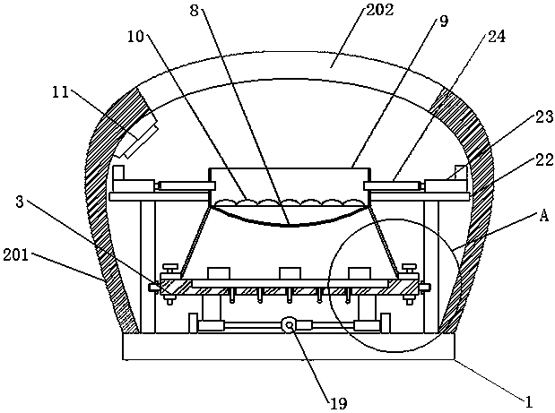
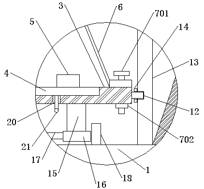
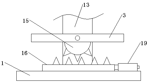

Image

  • LED automobile lamp
  • LED automobile lamp
  • LED automobile lamp

Examples


Embodiment Construction

[0035] The following will clearly and completely describe the technical solutions in the embodiments of the present invention in conjunction with the accompanying drawings in the embodiments of the present invention; obviously, the described embodiments are only part of the embodiments of the present invention, not all embodiments, based on The embodiments of the present invention and all other embodiments obtained by persons of ordinary skill in the art without making creative efforts belong to the protection scope of the present invention.

[0036] In the description of the present invention, it should be noted that the orientations or positional relationships indicated by the terms "upper", "lower", "inner", "outer", "top / bottom" etc. are based on the orientations shown in the drawings Or positional relationship is only for the convenience of describing the present invention and simplifying the description, but does not indicate or imply that the device or element referred t...


PUM


Abstract

The invention discloses an LED automobile lamp and belongs to the field of automobile parts. The LED automobile lamp comprises a main control module and a mounting substrate. A power module is connected to the main control module. A lamphousing is fixedly connected to one end of the mounting substrate. A heat conduction seat is arranged inside the lamp housing. An embedded groove is formed in theend, away from the mounting substrate, of the heat conduction seat. An LED lamp mounting plate is connected in the embedded groove. Three LED lamp sources are connected to the LED lamp mounting plate,wherein the three LED lamp sources are distributed uniformly. A luminance adjustment circuit is connected between the LED lamp sources and the main control module. A light gathering housing is connected to the end, close to the LED lamp sources, of the heat conduction seat. Assembling holes are formed in the light gathering housing and the heat conduction seat, wherein the assembling holes of thelight gathering housing correspond to those of the heat conduction seat. By means of the LED automobile lamp, a driver can start a high beam pertinently according to the practical environment condition conveniently; furthermore, the luminance, angel and illuminating range of the high beam can be adjusted properly; use flexibility of the high beam is improved prominently; the probability that a traffic accident is reduced; and energy conservation and environment protection are achieved.

Description

technical field [0001] The invention relates to the technical field of auto parts, and more specifically, relates to an LED vehicle lamp. Background technique [0002] Car lights refer to the lamps on the vehicle. The combination headlights of the car lights are on the front of the whole car. They mainly play the role of lighting and signals. The light emitted by the headlights can illuminate the road ahead According to the light source, the combination headlight can be divided into: halogen tungsten lamp, xenon lamp, and according to the function, it can be divided into high beam lamp, low beam lamp, front turn signal lamp, front position lamp ( The position light indicating the existence of the vehicle), the current national regulations on fog lights are not mandatory, it is optional, the combined tail light combined tail light is at the rear of the whole vehicle, mainly because it mainly plays the role of illumination and signal, the rear light is generally from the rear ...

Claims


Application Information

Patent Timeline
Patent Type & Authority Applications(China)
IPC IPC(8): F21S41/141F21S41/657F21S41/683F21S45/48F21V23/00F21V23/04F21S41/25F21S41/50F21W102/13F21W107/10F21Y115/10
CPCF21S41/141F21S41/25F21S41/50F21S41/657F21S41/683F21S45/48F21V23/003F21V23/0435F21V23/0464F21W2102/13F21W2107/10F21Y2115/10
Inventor 邓业泉
Owner 广州鸿志汽车配件有限公司
Learn More