Shell and tube heat exchanger

A heat exchanger, shell-and-tube technology, applied in the field of shell-and-tube heat exchangers, can solve problems such as single-function two-phase media

Inactive Publication Date: 2019-01-11
刘利康 +2
View PDF0 Cites 1 Cited by
  • Summary
  • Abstract
  • Description
  • Claims
  • Application Information

AI Technical Summary

Problems solved by technology

[0002] The finned heat exchangers used in domestic air conditioners rely on compressors for refrigeration and heating. The finned heat exchangers have a mature manufacturing process and a single application function. Arrange the fins in a rectangle and then pass the axial flow fan to force the air to exchange heat with the fins for the second time. At the same time, the cylindrical air flow of the axial flow fan will cause heat exchange dead angle to the non-circular fin heat exchanger and cannot make the two The phase medium is coaxial and reversed with the maximum temperature gradient method for high-efficiency heat exchange. The outdoor side fins are affected by air oxidation, dust, and water mist erosion all day long, and cannot be cleaned by physical methods. We can only rely on the design process to increase the fins in advance. The abundance of the heat exchange area of ​​the fins and the increase in the volume of the heat exchange diffusion space cannot offset the continuous reduction of heat exchange efficiency due to dirt because there is no economical and convenient physical cleaning and descaling means for non-erosion fins, so it can only be left to the refrigeration equipment. The energy efficiency ratio decreases continuously with the increase of the use time due to non-compressor reasons. Most of the heat energy of the outdoor side fin heat exchanger is consumed by the surrounding cold air during the electric defrosting process in winter, and the cold and hot sides of the refrigeration equipment pass through the reversing valve. The heat energy required for defrosting when switching over to perform defrosting operations, including the heat energy consumed by part of the outdoor air convection cooling energy during defrosting operations, must be provided by the conversion of indoor heat sources. The result is the finned heat exchanger itself. and the extension of the single application function attribute

Method used


Image

  • Shell and tube heat exchanger
  • Shell and tube heat exchanger

Examples


Embodiment 1

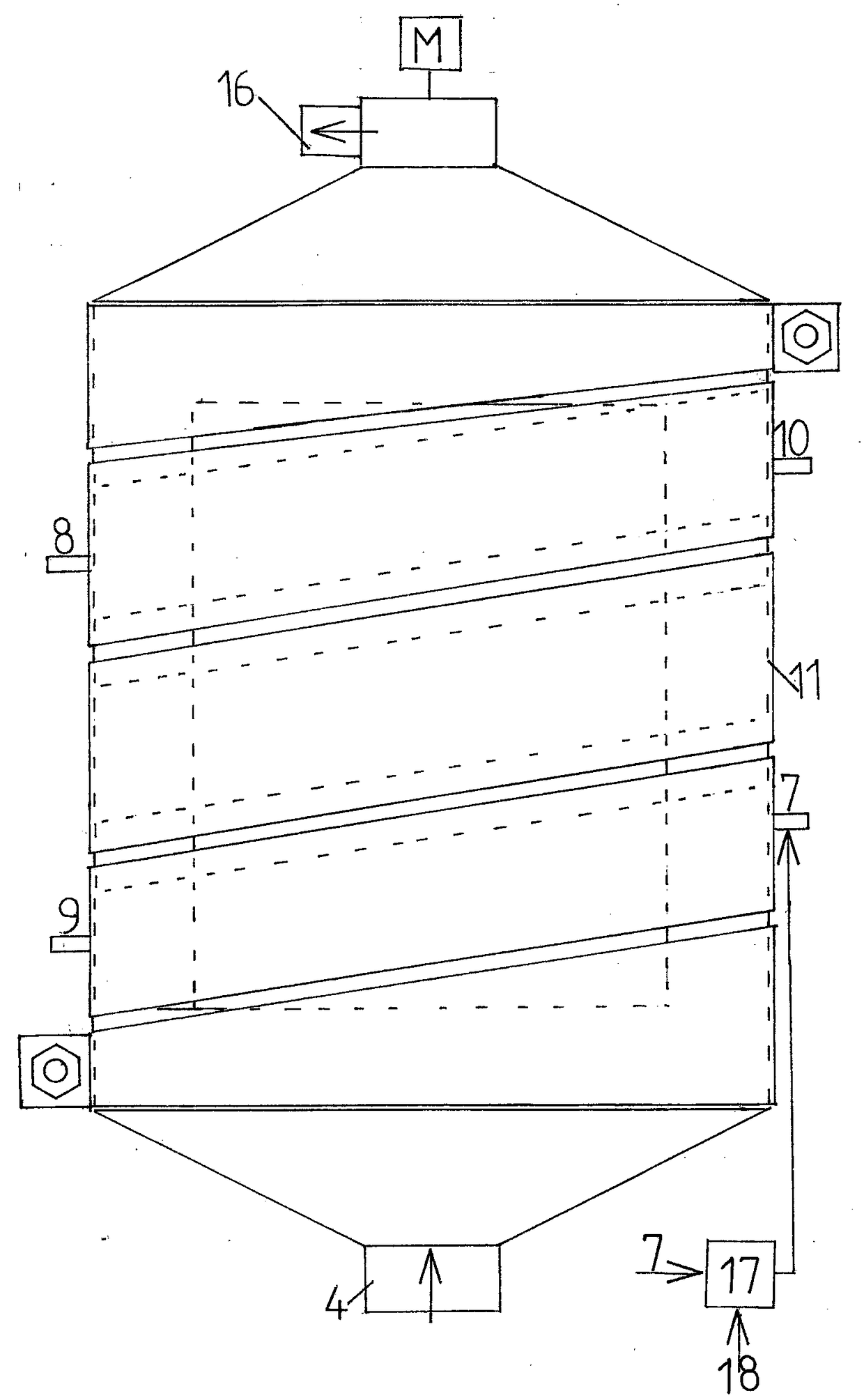
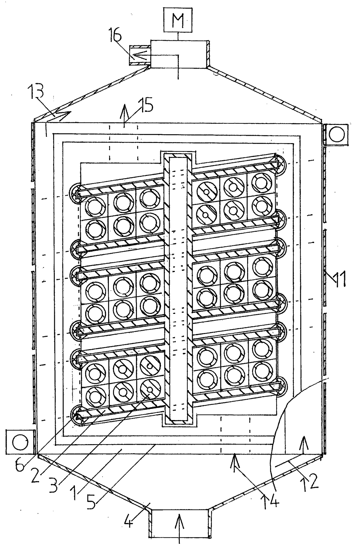
[0017] Such as figure 1 and figure 2 As shown, the spiral shell side 1) of the shell-and-tube heat exchanger in this embodiment, the double helix plate 2), the coil tube side 3), the spiral shell side air inlet 4, the shell side sealing groove 5, and the unilateral sealing line glue Quality sealing strip 6, shell side liquid medium inlet 7, shell side liquid medium outlet 8, tube side refrigerant inlet 9, tube side refrigerant outlet 10, steel spiral belt clamp 11, shell side outer spiral fin air inlet 12, shell side Outer helical fin heat exchange air outlet 13, double helix plate air inlet 14, double helix plate heat exchange air outlet 15, spiral shell side heat exchange air outlet 16, air-liquid medium automatic exchange valve 17, hot water level at the user end 18.

Embodiment 2

[0019] Install the spiral shell side sealing strip 5 on the half-side hollow semi-cylindrical rectangular plane of the spiral shell side 1, insert the outer side of the second-layer spiral plate of the double-helix plate 2 into the unilateral sealing line of the unilateral sealing line rubber sealing strip 6 and place the coil tube The tube pass 3 is installed on the corresponding spiral plate, and then the double helix plate 2 installed with the coil tube pass 3 is installed in the double helical groove corresponding to the half spiral shell pass 1, and the other half spiral shell pass 1 is installed to tighten the steel spiral belt clamp 11 Make the two hollow semicircular spiral shells into columns, install the air inlet 4 of the spiral shell and the heat exchange air outlet 16 of the spiral shell, connect the hot water level 18 at the user end to the automatic air-liquid interchange valve 17.

[0020] When using it specifically:

[0021] Connect the shell side liquid outle...


PUM


Abstract

The invention relates to a shell and tube heat exchanger. The shell and tube heat exchanger has the advantages that the ratio of the shell side size to the heat exchanging area is small, the air or low-viscosity liquid can serve as a heat exchanging medium, the entire process is free of dead band, short circuit and turbulence, maximum temperature gradient coaxial and reverse heat exchange with a tube side refrigerant medium is performed, the heat exchanger can be oppositely opened and is convenient to open and close, physical descaling and cleaning are performed on a shell side and a tube side, and the air or low-viscosity liquid medium can be automatically switched and exchanges heat with a tube side refrigerant.

Description

technical field [0001] The invention relates to a shell-and-tube heat exchanger, which belongs to the technical field of heat exchangers. Background technique [0002] The finned heat exchangers used in domestic air conditioners rely on compressors for refrigeration and heating. The finned heat exchangers have a mature manufacturing process and a single application function. Arrange the fins in a rectangle and then pass the axial flow fan to force the air to exchange heat with the fins for the second time. At the same time, the cylindrical air flow of the axial flow fan will cause heat exchange dead angle to the non-circular fin heat exchanger and cannot make the two The phase medium is coaxial and reversed with the maximum temperature gradient method for high-efficiency heat exchange. The outdoor side fins are affected by air oxidation, dust, and water mist erosion all day long, and cannot be cleaned by physical methods. We can only rely on the design process to increase th...

Claims


Application Information

Patent Timeline
Patent Type & Authority Applications(China)
IPC IPC(8): F28D7/04
CPCF28D7/04F28D2021/0068
Inventor 刘利康刘鸣刘佳嘉
Owner 刘利康
Why Eureka
Try Eureka