Ground penetrating radar in device for measuring primary support with measuring wheel

A technology of ground penetrating radar and measurement wheel, which is applied in measurement devices, radio wave measurement systems, and re-radiation, etc., can solve the problems that distance cannot represent the measurement mileage, cannot fully represent the real situation, and cannot be coupled, so as to reduce labor consumption. , The effect of accurate measurement and improved efficiency

Pending Publication Date: 2019-01-11
SHANDONG UNIV +1
5 Cites 1 Cited by

AI-Extracted Technical Summary

Problems solved by technology

[0005] When the existing device measures the initial support, because the measuring wheel and the radar system are fixed, the measuring wheel cannot be well coupled with the contact surface when it contacts the concave lining, so that the distance reflected by the measuring wheel cannot represent the rea...

Method used

Measuring wheel, utilizes linear elastic hook type spring 10 to hook up with 9 places of georadar hook mutually, makes connecting rod, georadar, measuring wheel constitute the elastic firm system that can rotate around fulcrum and can restore original shape. This better couples the measuring wheel to the contact surface. Make the transmitted data more accurate.
[0035] The damping hinge 16 utilizes a shaping connecting plate and a bolt to connect one end of the hinge to the radar, and simultaneously each bolt connection uses a spring washer to alleviate the bufferi...

Abstract

The invention discloses a ground penetrating radar in a device for measuring a primary support with a measuring wheel, comprising a ground penetrating radar and a measuring wheel, wherein a signal acquisition device is mounted on the measuring wheel, and the signal acquisition device is connected to the ground penetrating radar; the drive shaft of the measuring wheel is connected to one end of a damping hinge horizontally fixed to the top of the ground penetrating radar through a telescopic link, the other end of the damping hinge is connected to the ground penetrating radar; the telescopic link can rotate with the drive shaft; the drive shaft is also connected to the side wall of the ground penetrating radar through a horizontal elastic device; the elastic device, the telescopic link andthe ground penetrating radar form a triangle, so that the measuring wheel forms a stable system with the ground penetrating radar during the traveling process to measure; and the signal acquisition device mounted on the measuring wheel is connected to the ground penetrating radar.

Application Domain

Radio wave reradiation/reflection

Technology Topic

PhysicsHinge angle +4

Image

  • Ground penetrating radar in device for measuring primary support with measuring wheel
  • Ground penetrating radar in device for measuring primary support with measuring wheel
  • Ground penetrating radar in device for measuring primary support with measuring wheel

Examples

  • Experimental program(1)

Example Embodiment

[0026] It should be noted that the following detailed description is exemplary and intended to provide further explanation of the application. Unless otherwise defined, all technical and scientific terms used herein have the same meaning as commonly understood by one of ordinary skill in the art to which this application belongs.
[0027] It should be noted that the terminology used herein is for the purpose of describing specific embodiments only, and is not intended to limit the exemplary embodiments according to the present application. As used herein, unless the context clearly dictates otherwise, the singular is intended to include the plural as well, furthermore, it is to be understood that when the terms "comprising" and/or "including" are used in this specification, it indicates that the presence of features, steps, operations, devices, components and/or combinations thereof;
[0028] For the convenience of description, if the words "up", "down", "left" and "right" appear in the present invention, it only means that the directions of up, down, left and right are consistent with the drawings themselves, and do not limit the structure. It is for the convenience of describing the present invention and simplifying the description, rather than indicating or implying that the device or element referred to must have a specific orientation, be constructed and operate in a specific orientation, and therefore should not be construed as a limitation of the present invention.
[0029] As described in the background art, for GPR, how to use DISTANCE in MODE for more efficient and accurate measurement and feedback data is the key to better coupling between the rotation of the measuring wheel and the contact surface.
[0030] When the existing device measures the initial support, since the measuring wheel is fixed to the radar system, when the measuring wheel contacts the concave lining, it cannot be well coupled with the contact surface, so that the distance reflected by the measuring wheel cannot represent the actual measurement mileage in the actual measurement. At the same time, because the measuring wheel cannot be well coupled with the contact surface, the experimental data fed back deviates from the real situation behind the initial support, and cannot fully represent and reflect the real situation after lining. Therefore, it is necessary to further study the method of measuring the initial branch of the ground penetrating radar using the measuring wheel. In order to solve the above technical problem, the present application proposes a device for measuring the initial branch of the ground penetrating radar using the measuring wheel.
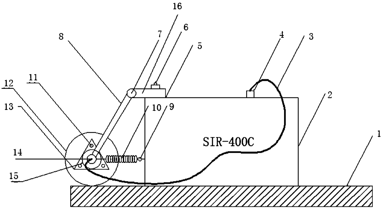
[0031] In a typical embodiment of the present application, such as figure 1 As shown in the figure, the ground penetrating radar uses the measuring wheel to measure the initial support device to realize the connection between the ground penetrating radar and the measuring wheel by using a damping hinge. A triangle is formed, so that the measurement wheel and the ground penetrating radar form a stable system for measurement during the traveling process. The specific structure is as follows:
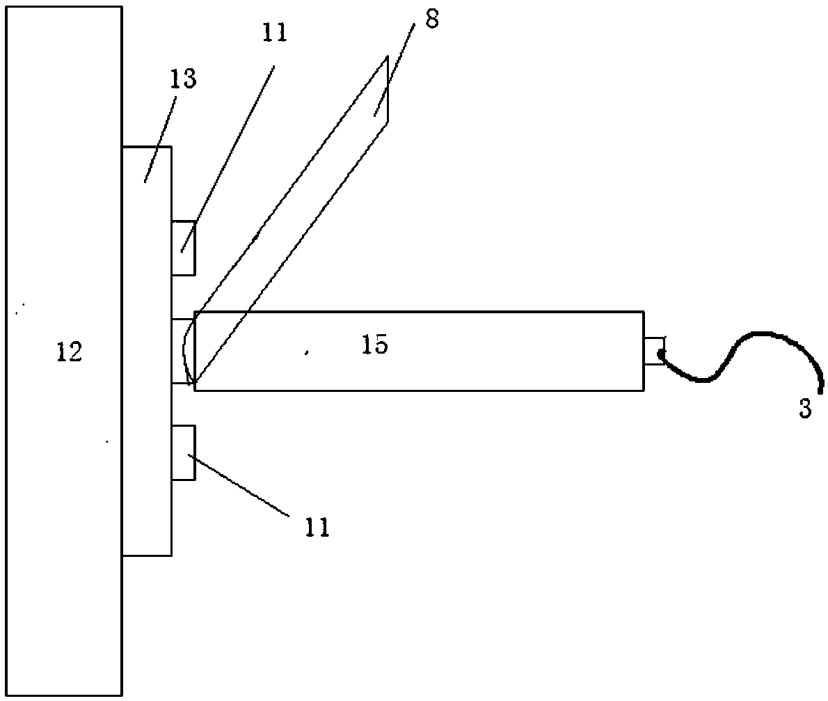
[0032] The ground penetrating radar uses the measuring wheel to measure the first branch device, including the ground penetrating radar 2 and the measuring wheel 12, on the measuring wheel 12 is installed a signal collecting device 15, the signal collecting device 15 and the ground penetrating radar 2 The connection holes 4 are connected by wires 3;
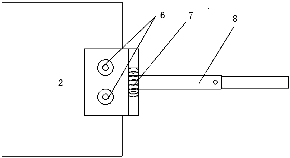
[0033] The drive shaft of the measuring wheel is connected to one end of a damping hinge 5 horizontally fixed on the top of the ground penetrating radar through a retractable connecting rod 8, and the end of the damping hinge is in a suspended state; the other end of the damping hinge is connected to the ground penetrating radar; so The telescopic link can be rotated together with the drive shaft 7;
[0034] The drive shaft is also connected to the side wall of the ground penetrating radar 2 through a horizontally arranged spring hook 9, and the elastic device, the retractable connecting rod and the ground penetrating radar form a triangle, so that the measuring wheel is connected to the ground penetrating radar during the traveling process. A stable system is formed for measurement; and the signal acquisition device installed on the measurement wheel is connected with the ground penetrating radar.
[0035] The damping hinge 16 uses a plastic connecting plate and bolts to connect one end of the hinge to the radar, and a spring washer is used at each bolt connection to reduce the buffering effect.
[0036] The connection shaft of the damping hinge 16 and the telescopic link 8 adopts a spring-loaded rotating shaft similar to the door rotation, which plays the role of rotating with the link.
[0037] The retractable connecting rod 8 adopts a light connecting rod with a buffer, the connecting rod is retractable, and the telescopic device is the same as the umbrella telescopic rod. So that the connecting rod can rotate with the measuring wheel, better free expansion and contact surface coupling.
[0038] The signal acquisition device 15 is connected through the triangular plate connecting plate 13, the bolt 11 and the measuring wheel 12, and at the same time, the spring washer is used to reduce mutual friction and reduce the buffering effect.
[0039] The measuring wheel uses a linear elastic hook-type spring 10 to hook each other with the geological radar hook 9, so that the connecting rod, the geological radar and the measuring wheel form an elastic and stable system that can rotate around the fulcrum and can restore the original shape. This allows better coupling of the measuring wheel to the contact surface. Make the transmitted data more accurate.
[0040]Instructions for use of specific implementations:
[0041] When the measuring wheel 12 contacts the uneven contact surface 1 , it first drives the telescopic link 8 to expand and contract. At this time, the lower end hook spring 10 is linearly elastically elongated along with the telescopic link 8 and the measuring wheel 12 .
[0042] The buffer provided in the retractable link 8 and the hook type 9 spring 10 at the lower end make the whole device in the property of restoring the original state at any time, but because the fulcrum (measuring wheel) is coupled with the initial support surface 1 due to friction, The telescopic link 8 and the spring 10 will continue to be in a linear elastic expansion state. In this way, the whole system is free to expand and contract and the contact surface is coupled. When the instrument is separated from the contact surface, the spring 10 first restores its original length under the action of linear elasticity, and drives the connecting rod to compress. Restore the original instrument state.
[0043] The pivot shaft 7 at the hinge, which is similar to the pivot of the door, plays a key role in fitting.
[0044] Compared with the prior art, the beneficial effects of the present invention are:
[0045] 1) The device is simple and easy to operate, easy to carry, and uses a simple mechanical hinge and a linear elastic spring to enable the measuring wheel to be coupled with the contact surface of the primary support
[0046] 2) The whole device system belongs to the state of automatic extension and compression, which can be matched with the measuring wheel with the change of the curvature of the measuring wheel and the contact surface. At the same time, the structure is under the geometric invariant system of the triangle, which has good stability and invariance.
[0047] 3) The device can better play the actual role of the measuring wheel, making the measurement more accurate.
[0048] 4) The device of the present invention is simple in structure and setup, does not require complicated construction procedures, can reduce labor consumption, and is easy to operate and improve efficiency.
[0049] The above descriptions are only preferred embodiments of the present application, and are not intended to limit the present application. For those skilled in the art, the present application may have various modifications and changes. Any modification, equivalent replacement, improvement, etc. made within the spirit and principle of this application shall be included within the protection scope of this application.

PUM

no PUM

Description & Claims & Application Information

We can also present the details of the Description, Claims and Application information to help users get a comprehensive understanding of the technical details of the patent, such as background art, summary of invention, brief description of drawings, description of embodiments, and other original content. On the other hand, users can also determine the specific scope of protection of the technology through the list of claims; as well as understand the changes in the life cycle of the technology with the presentation of the patent timeline. Login to view more.

Similar technology patents

Novel Fenton reaction device

Owner:GUANGDONG UNIV OF PETROCHEMICAL TECH

Classification and recommendation of technical efficacy words

  • easy to carry
  • Simple installation

Abnormity monitoring method and abnormity monitoring device

ActiveCN103377094Aeasy to carry
Owner:KINGDEE SOFTWARE(CHINA) CO LTD

Bluetooth communication bracelet

ActiveCN103815628Aeasy to carryeasy to answer
Owner:1MORE ACOUSTIC TECH CO LTD

Display device and electronic product

ActiveCN108520702ASatisfy the big screen and big field of vieweasy to carry
Owner:GUANGZHOU GOVISIONOX TECH CO LTD
Why Eureka
Try Eureka