Laser radar system

A technology of laser radar and light source, which is applied in radio wave measurement system, electromagnetic wave re-radiation, utilization of re-radiation, etc., can solve the problem that the influence cannot be eliminated, and achieve the effect of fast and efficient modulation and suppression of influence

Pending Publication Date: 2019-01-11
ZVISION TECH CO LTD
View PDF3 Cites 34 Cited by
  • Summary
  • Abstract
  • Description
  • Claims
  • Application Information

AI Technical Summary

Problems solved by technology

Using a two-dimensional detector array can improve the resolution, signal-to-noise ratio and detection distance to a certain extent, but it still cannot eliminate the influence of interfering light in the environment on the signal-to-noise ratio

Method used


Image

  • Laser radar system
  • Laser radar system
  • Laser radar system

Examples


no. 1 example

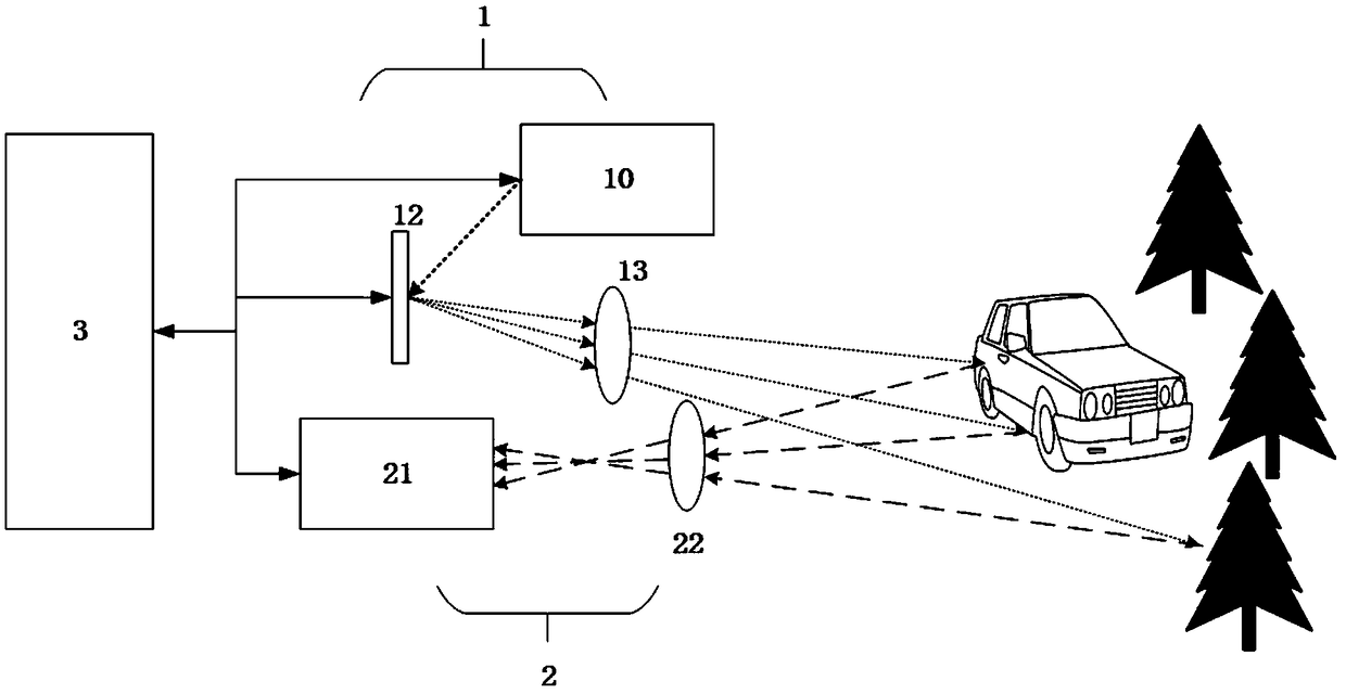
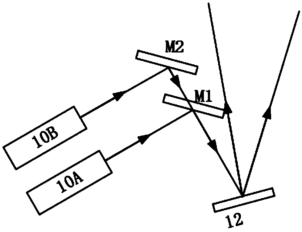
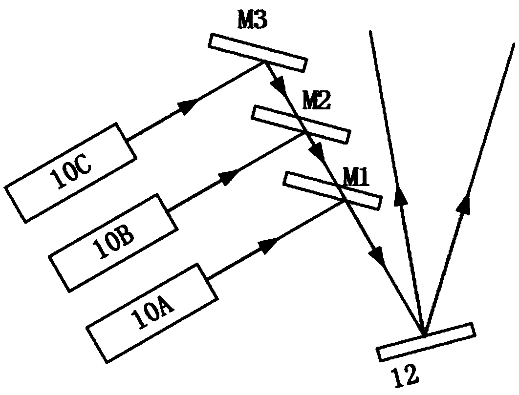
[0049] see Figure 2a , According to the first embodiment of the light emitting unit of the present invention, the light emitting unit 1 includes a first light source A and a second light source B, a first mirror M1 and a second mirror M2 and a scanning unit 12 . The first mirror M1 includes opposing first and second surfaces. The light emitted by the first light source A is reflected by the first surface of the first mirror M1 and reaches the scanning unit 12 . The light emitted by the second light source B is reflected by the second reflector M2 and then reaches the second surface of the first reflector M1 , and then reaches the scanning unit 12 after being transmitted by the second surface of the first reflector M1 .

[0050] Figure 2a A schematic diagram of the light path of the first embodiment of the light emitting unit according to the present invention is shown. The light emitting unit 1 includes a light source A and a light source B, and mirrors M1 and M2 correspo...

no. 4 example

[0054] see Figure 3a , according to the fourth embodiment of the light emitting unit of the present invention, the light emitting unit 1 includes a first light source A and a second light source B, a polarization beam splitting / combining prism (PBS) and a scanning unit 12 . The polarization directions of the lights respectively emitted by the first light source A and the second light source B are perpendicular to each other. The light emitted from the light source A is completely reflected by the PBS and irradiated to the scanning unit 12 . The light emitted from the light source B is completely transmitted by the PBS and irradiated to the same scanning unit 12 . The light paths from light source A and light source B after passing through the PBS overlap. In this way, the light reflected from the light source A via the PBS and the light transmitted from the light source B via the PBS arrive at the same scanning point on the scanning unit.

[0055] The light source A and th...


PUM


Abstract

The invention relates to a laser radar system. The laser radar system comprises a light emitting unit, a light receiving unit and a control unit, wherein the light emitting unit comprises a light source and a scanning unit, and the scanning unit is configured to reflect light from the light source at a controllable deflection angle to scan a target object; the light receiving unit is used for receiving the light reflected from the target object and outputting a detection value, and the light receiving unit comprises a photoelectric sensor device; and a light path from the light emitted by thelight emitting unit to the target object is non-coaxial with a light path from the light reflected from the target object to the light receiving unit. According to the laser radar system, the defect that an SPAD detector in an optical sensor cannot eliminate dark counts in the prior art is overcome; distance information of a surrounding three-dimensional space environment can be accurately measured; and the influence of background light and other stray light can be greatly inhibited, so that spatial light can be quickly and efficiently modulated.

Description

technical field [0001] The present invention relates to a laser radar system, in particular to a non-coaxial receiving laser radar system. Background technique [0002] Lidar (LIDAR) measures the position, speed, and other information of a target object by emitting a laser beam to the target object and receiving the beam reflected from the target object. Current lidar systems typically use a single photodetector or a one-dimensional photodetector array (a row of photodetectors or a column of laser detectors) to receive the reflected beam. The light-receiving surface of a photodetector is often larger than the spot size of the reflected beam. In the light reaching the light-receiving surface of the photodetector, in addition to the desired reflected light from the target object, there may also be interfering light from other objects in the field of view (FOV) (for example, strong sunlight, or from other LiDAR system beam). When the lidar is applied to a high-speed, long-di...

Claims


Application Information

Patent Timeline
Patent Type & Authority Applications(China)
IPC IPC(8): G01S17/08G01S7/481
CPCG01S7/481G01S17/08G01S7/4816G01S7/4815G01S7/4817G01S17/42G01S7/4863G01S7/484G01S7/4861
Inventor 石拓夏冰冰刘佳尧
Owner ZVISION TECH CO LTD
Why Eureka
Try Eureka