
Arc generating equipment and method for evaluating arc ablation resistance of electrical contact materials

A technology for generating equipment and electric contacts, which is applied in the field of electrical testing, can solve problems such as the inability to meet the evaluation requirements of electric contacts, and the lack of arc generation equipment, etc., to control charging time, reduce selection requirements, and reduce excessive charging current Effect

Active Publication Date: 2019-01-11
GLOBAL ENERGY INTERCONNECTION RES INST CO LTD +2
View PDF2 Cites 13 Cited by
  • Summary
  • Abstract
  • Description
  • Claims
  • Application Information

AI Technical Summary

Problems solved by technology

[0004] Therefore, the technical problem to be solved by the present invention is to solve the problem that there is no mature arc generating equipment in the prior art and cannot meet the evaluation requirements for electrical contacts

Method used


Image

  • Arc generating equipment and method for evaluating arc ablation resistance of electrical contact materials
  • Arc generating equipment and method for evaluating arc ablation resistance of electrical contact materials
  • Arc generating equipment and method for evaluating arc ablation resistance of electrical contact materials

Examples


Embodiment 1

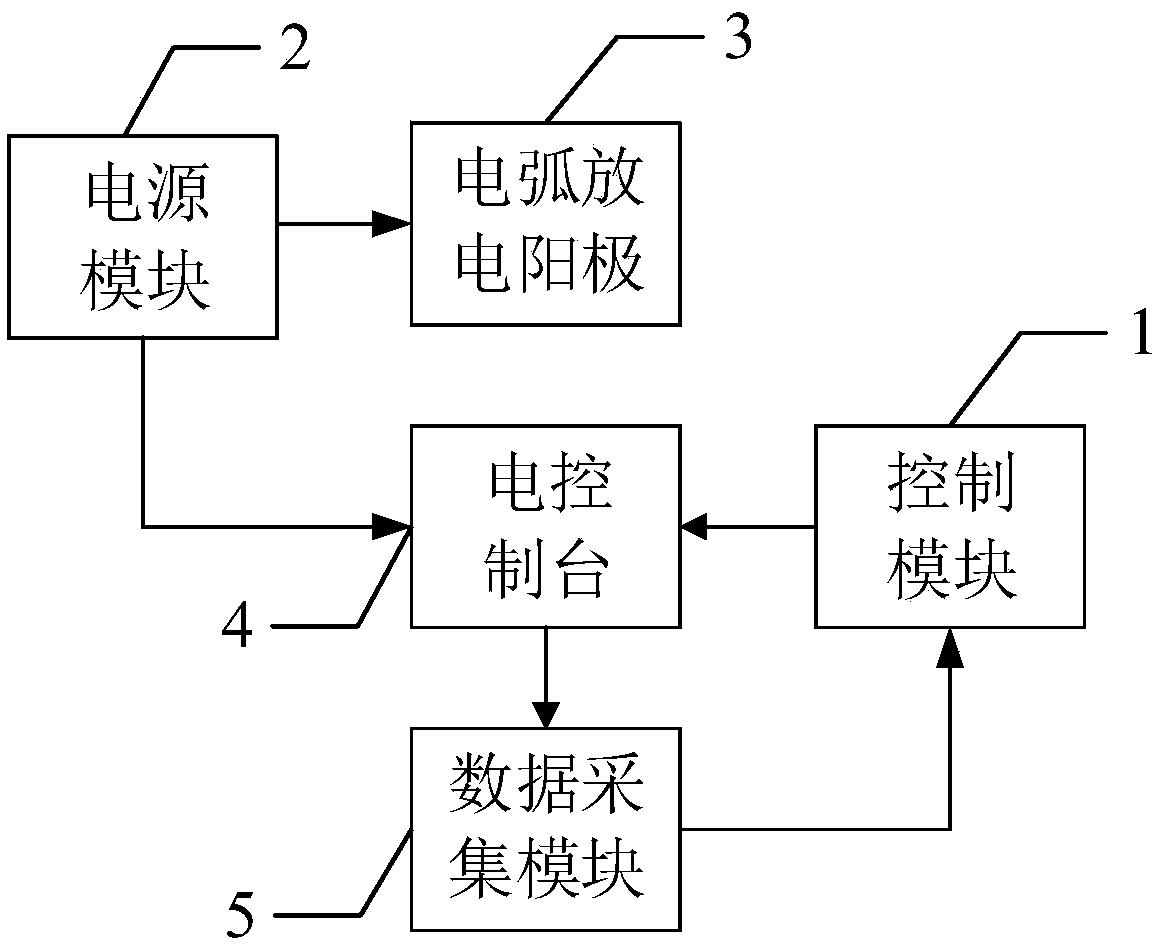
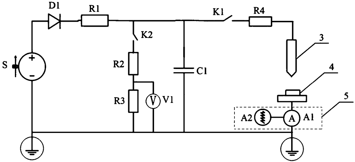
[0030] This embodiment provides an arc generating device, such as figure 1 As shown, it includes: a control module 1, a power module 2, an arc discharge anode 3, an electric console 4 and a data acquisition module 5.

[0031] Wherein, the anode of the power module 2 is connected with the arc discharge anode 3, and the cathode is connected with the sample of the electric contact provided on the electric console 4 to provide the arc discharge voltage; the electric console 4 is connected with the control module 1. connected to be close to or away from the arc discharge anode 3 according to the output signal of the control module 1; the data acquisition module 5 is arranged between the cathode of the power module 2 and the electric console 4, and is connected with the control module 1 to collect the arc discharge current during the discharge process, and send the discharge current to the control module 1.

[0032] In this embodiment, in order to meet the requirement that the arc ...

Embodiment 2

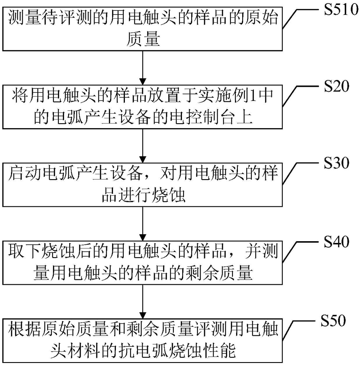
[0048] This embodiment provides a method for evaluating the arc ablation resistance performance of electrical contact materials, such as image 3 shown. It should be noted that this method is an application method of the arc generating device in Embodiment 1, and what has been explained in Embodiment 1 will not be repeated here. In addition, although the logical sequence is shown in the flow chart, In some cases, however, the steps shown or described may be performed in an order different from that presented here. The process includes the following steps:

[0049] Step S10, measuring the original quality of the sample to be evaluated for the electrical contact. In this embodiment, the sample needs to be made into a metallographic sample, and the surface is mechanically polished, and then ultrasonically cleaned in deionized water to remove oil stains on the sample surface, and dried. In this embodiment, a high-density electronic balance is used for weighing samples.

[0050...


PUM

PropertyMeasurementUnit
Diameteraaaaaaaaaa
Thicknessaaaaaaaaaa
Radiusaaaaaaaaaa

Abstract

The invention discloses an arc generating device and an electric contact material anti-arc ablation performance evaluation method. The arc generating device comprises a control module, a power supplymodule, an arc discharge anode, an electric console and a data acquisition module, wherein the anode of the power supply module is connected with the arc discharge anode, and the cathode is connectedwith a sample of an electric contact arranged on the electric control table, so as to provide an arc discharge voltage. The electric console is connected with the control module for approaching or removing the arc discharge anode according to the output signal of the control module. The data acquisition module is arranged between the cathode of the power supply module and the electric console, andis connected with the control module, so as to collect the discharge current in the arc discharge process and send the discharge current to the control module. When the distance between the electricconsole and the arc discharge anode is adjusted by the control module to meet the condition, an arc breakdown discharge can be carried out between the arc discharge anode and the sample of the electric contact in the arc generating apparatus.

Description

technical field [0001] The invention relates to the technical field of electrical detection, in particular to an arc generating device and a method for evaluating the anti-arc ablation performance of electric contact materials. Background technique [0002] The contact is one of the key components of the switching device. The main performance and life of the switching device depend to a large extent on the quality of the contact material. With the development of large-capacity ultra-high voltage transmission and transformation grids, the low-voltage power distribution system and control system have higher requirements for automation and sensitivity, and the upgrading of electronic industrial products, the instrument and electrical switches are also moving towards high voltage, high current and The direction of miniaturization is developing, and because the breaking current of the instrument electrical switch is larger, the arc burning is more intense, and the requirements fo...

Claims


Application Information

Patent Timeline
IPC IPC(8): H01T19/04G01N5/00G01N5/04
CPCG01N5/00G01N5/04H01T19/04
Inventor 丁一祝志祥陈保安张强韩钰王强陈新马光陈川孙亮刘昕
Owner GLOBAL ENERGY INTERCONNECTION RES INST CO LTD
Learn More