
Self-power-generating energy-saving pruning shear

A technology of pruning shears and self-generating power, which is applied in current collectors, electromechanical devices, electric vehicles, etc. It can solve problems such as laborious, inconvenient use, and inability to cut thick branches, and achieve the effect of improving battery life

Active Publication Date: 2019-01-15
永康市金箭金属制品有限公司
View PDF7 Cites 3 Cited by
  • Summary
  • Abstract
  • Description
  • Claims
  • Application Information

AI Technical Summary

Problems solved by technology

The most commonly used pruning shears are similar to scissors, including two rotating arms that are hinged to each other. One side of the two rotating arms at the hinged position is a cutting edge that cooperates with each other, and the other side is a handle, usually between the two handles. There is a spring that pops up the rotating arm between them. This kind of pruning shears is light in structure, easy to carry and easy to operate. This kind of pruning shears is easy to prune thin branches, but it is very laborious when pruning thick branches, even because of lack of strength. Unable to cut off thick branches, overall laborious when pruning both thick and thin branches
[0003] In order to make pruning shears more labor-saving, especially when pruning thick branches, electric pruning shears have appeared. Existing electric pruning shears generally include fixed blades, rotating blades, driving mechanisms, and battery components or power cords. One of the components, if the battery is used to provide power to the drive mechanism, the battery life is poor or the weight of the battery is large, which will cause inconvenience in use; while the power cord component directly connected to the circuit requires a very long power cord, which is not suitable for outdoor orchards Use of other places

Method used


Image

  • Self-power-generating energy-saving pruning shear
  • Self-power-generating energy-saving pruning shear

Examples


Embodiment Construction

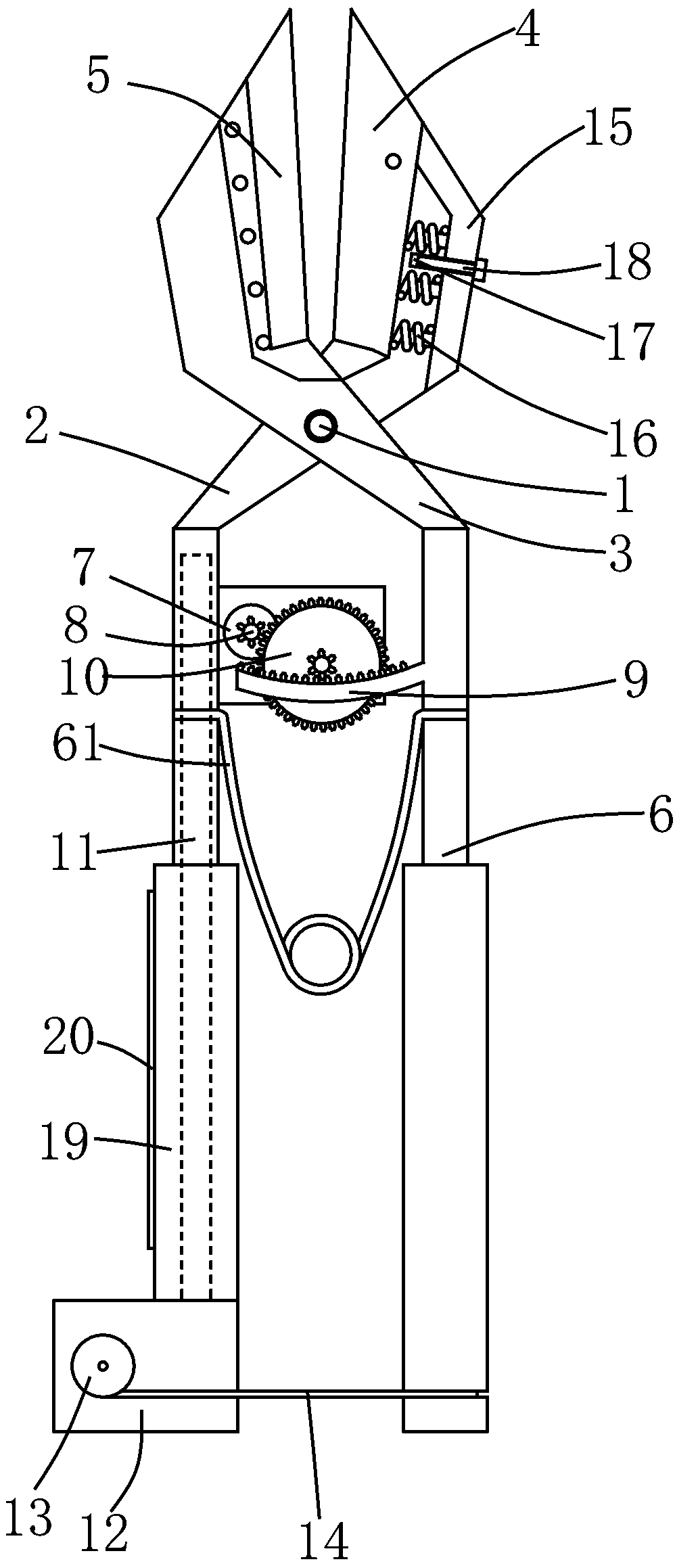
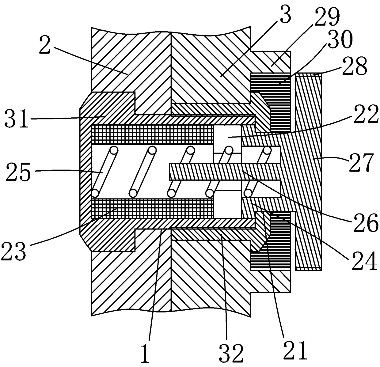
[0014] The present invention will be described in further detail below in conjunction with accompanying drawing and specific embodiment: see Figure 1 to Figure 2 , a kind of self-generating energy-saving pruning shears, including a first rotating arm 2 and a second rotating arm 3 hinged to each other through a hinge 1, the first rotating arm 2 and the second rotating arm 3 are located at the hinged position One side is respectively provided with a first cutting edge 4 and a second cutting edge 5 which cooperate with each other, and the other side of the first rotating arm 2 and the second rotating arm 3 at the hinged position is a handle 6, the A first spring 61 that bounces off the first rotating arm 2 and the second rotating arm 3 is provided between the handles 6, and the first rotating arm 2 is provided with a power generation assembly 7, and the power generation assembly 7 The rotating shaft is connected with a first gear 8 through a one-way bearing, and the second rotat...


PUM


Abstract

The invention discloses a self-power-generating energy-saving pruning shear, comprising a first rotating arm and a second rotating arm which are hinged to each other, and the first rotating arm and the second rotating arm are provided with a first cutting edge and a second cutting edge. First springs are arranged on hand-held portions, the first rotating arm is provided with a power generating component, the second rotating arm is provided with a curved rack, and the first rotating arm is provided with a battery connected with the power generating component. A winding motor is disposed on thefirst rotating arm, a winding wheel is disposed on the winding motor, and a pulling rope is connected between the winding wheel and the second rotating arm. The first cutting edge is rotatably connected to the first rotating arm, the first rotating arm is provided with a limiting protrusion, and a second spring is disposed between the limiting protrusion and the first cutting edge. One side of therotation center of the first cutting edge abuts against the other side of the second spring and against the limiting protrusion, and the limiting protrusion is provided with a contact switch. This pruning shear not only achieves the requirements of light weight, but also enhances the endurance ability and achieves the purpose of saving energy.

Description

technical field [0001] The invention belongs to the technical field of branch pruning tools, in particular to a self-generating energy-saving pruning shears, which are used for pruning fruit trees and gardening branches. Background technique [0002] Pruning shears are tools used for fruit tree branch pruning and garden tree branch pruning. The most commonly used pruning shears are similar to scissors, including two rotating arms that are hinged to each other. One side of the two rotating arms at the hinged position is a cutting edge that cooperates with each other, and the other side is a handle, usually between the two handles. There is a spring that pops up the rotating arm between them. This kind of pruning shears is light in structure, easy to carry and easy to operate. This kind of pruning shears is easy to prune thin branches, but it is very laborious when pruning thick branches, even because of lack of strength. It is impossible to cut off thick branches, and it is ...

Claims


Application Information

Patent Timeline
Patent Type & Authority Applications(China)
IPC IPC(8): A01G3/037H02J7/32H02K7/18
CPCA01G3/037H02J7/32H02K7/1861
Inventor 黄烨昆
Owner 永康市金箭金属制品有限公司
Learn More