A connector automatic riveting device

A riveting device and connector technology, applied in the manufacture of vehicle connectors, contact boxes/bases, etc., can solve the problems of increased waiting, transmission delay time, low work efficiency, affecting the quality of connector installation, etc., and reduce manual operation. Intensity and labor costs, the effect of a high degree of automation

Active Publication Date: 2022-04-29
SHENZHEN WOER HEAT SHRINKABLE MATERIAL +1
View PDF6 Cites 0 Cited by
  • Summary
  • Abstract
  • Description
  • Claims
  • Application Information

AI Technical Summary

Problems solved by technology

[0006] One is that the pressure at the contact point of the installer’s fingers is too high. After a long-term riveting operation with such precise requirements and high stress, it is easy to cause fatigue and pain, which will affect the consistency of the connector’s installation quality; The installation and coordination precision requirements between the two parts are high, the assembly and riveting cannot be completed in one process, and the transfer and connection process needs to be subdivided, which increases the waiting and transmission delay time between actions, and the work efficiency is low
Therefore, these two methods can only be applied to small-scale production in workshops, and it is difficult to adapt to the requirements of modern industrial production.

Method used


Image

  • A connector automatic riveting device
  • A connector automatic riveting device
  • A connector automatic riveting device

Examples


Embodiment Construction

[0050] In order to describe in detail the technical content, structural features, achieved goals and effects of an automatic riveting device for connectors of the present invention, the following will be further described in conjunction with the embodiments and accompanying drawings.

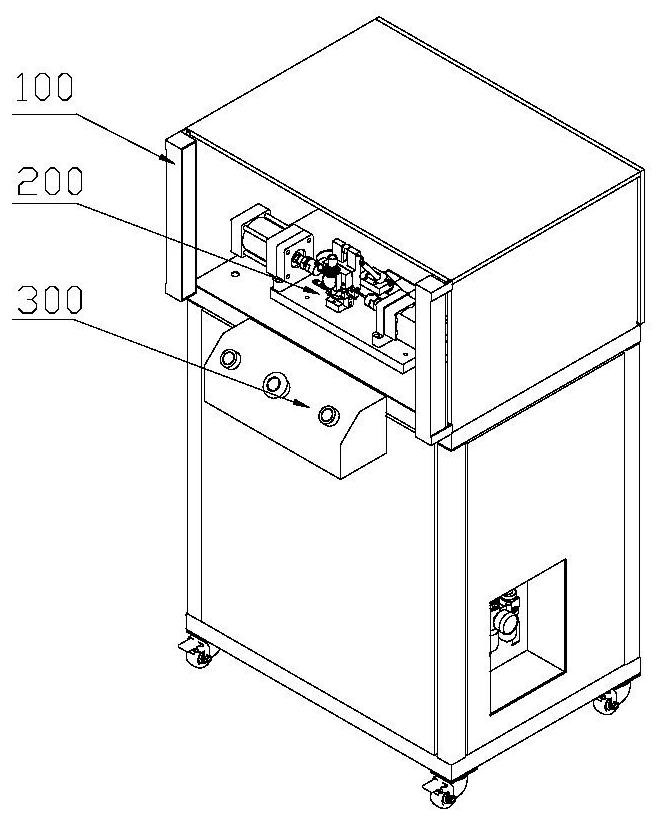
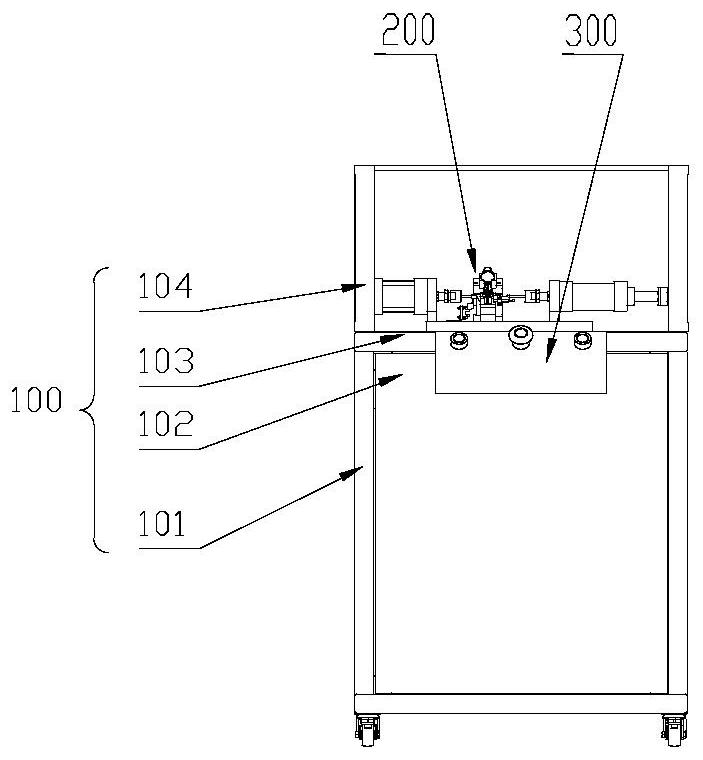
[0051] Such as Figure 1 to Figure 9 As shown, an embodiment of an automatic riveting device for connectors of the present invention is disclosed, including: a frame 100, an automatic riveting mechanism 200, and an operation control mechanism 300; The automatic riveting mechanism 200 is surrounded by the cover plate 102 of the frame 100 ; the button shell 301 of the operation control mechanism 300 is welded to the frame 100 .

[0052] Wherein, the rack 100 further includes: a frame body 101, a cover plate 102, a support plate 103, and a grating post 104; the frame body 101 fastens and connects the cover plate 102, the support plate 103, and the grating post 104 into a whole by screws.

[0053] ...


PUM


Abstract

The invention discloses an automatic riveting device for a connector, which comprises a frame, an automatic riveting mechanism, and an operation control mechanism; a support plate on the frame is fastened to a mounting seat plate of the automatic riveting mechanism; Surrounded by the cover plate; the button shell of the operation control mechanism is fixed on the frame; the riveting cylinder and the nail feeding cylinder of the automatic riveting mechanism are fixedly connected with the riveting cylinder seat and the nail feeding cylinder seat respectively; the turning cylinder and the turning cylinder of the automatic riveting mechanism The seat is fixedly connected, and then the whole is connected with the cylinder turning fixed seat by the first straight pin or the first hinge, and the piston rod of the turning cylinder is connected with the turning plate or the second hinge through the connector, the fish eye bearing, the second straight pin. The connection between the connector body and buckle, torsion spring, rivet and its riveting action are completed at one time, which significantly reduces the intensity of manual operation and labor cost, and can lay a technical module for the design of standardized and fully automated production lines.

Description

technical field [0001] The invention belongs to the field of automatic fixtures used for installation with electric vehicle charging connectors and similar products, and in particular relates to an automatic riveting device for connectors. Background technique [0002] Such as Figure 10 with Figure 11 As shown, it is an example of a current electric vehicle used for the male end connector of the charging gun. When in use, the male-end connector is mated with the female-end connector, and the buckle is fastened with the corresponding position of the female-end to prevent loosening, so as to ensure that the photoelectric circuit is always in a safe and stable connection state; if it needs to be disassembled For maintenance, press and hold the buckle sleeve, lift the buckle to get out of the buckled state, pull out the male connector, and get out of the mating connection. [0003] In the manufacturing process and installation process of this type of electric vehicle chargin...

Claims


Application Information

Patent Timeline
Patent Type & Authority Patents(China)
IPC IPC(8): B21J15/14B21J15/20B21J15/28B21J15/32H01R43/18
CPCH01R43/18B21J15/14B21J15/20B21J15/28B21J15/32B21J15/38H01R2201/26
Inventor 魏任升汪家伟张维波曹小金康树峰
Owner SHENZHEN WOER HEAT SHRINKABLE MATERIAL
Why Eureka
Try Eureka