
Angle gear high-temperature tin alloy liquid furnace

A tin alloy and gear technology, applied in the field of angle gear high temperature tin alloy liquid furnace, can solve the problems of the impeller tin temperature and tin temperature cannot be guaranteed, the tin liquid spraying is not smooth, the welding quality is degraded, etc., to achieve reliable and stable temperature parameters, Improve the effect of using orders and maintaining consistent temperature

Pending Publication Date: 2019-01-15
深圳普洲自动化设备有限公司
View PDF0 Cites 0 Cited by
  • Summary
  • Abstract
  • Description
  • Claims
  • Application Information

AI Technical Summary

Problems solved by technology

1. When the temperature is too high, the belt will loosen, and the tin liquid will not be ejected smoothly, resulting in a decline in welding quality or the need to replace the belt, which will affect production efficiency.
2. The distance between the impeller and the nozzle opening is relatively large, which can easily cause uneven temperature, and it is impossible to ensure that the temperature of the tin sucked by the impeller is consistent with the temperature of the tin outlet

Method used


Image

  • Angle gear high-temperature tin alloy liquid furnace
  • Angle gear high-temperature tin alloy liquid furnace

Examples


Embodiment 1

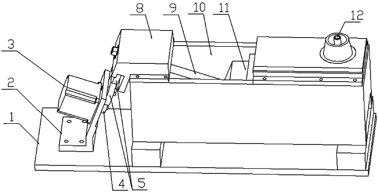
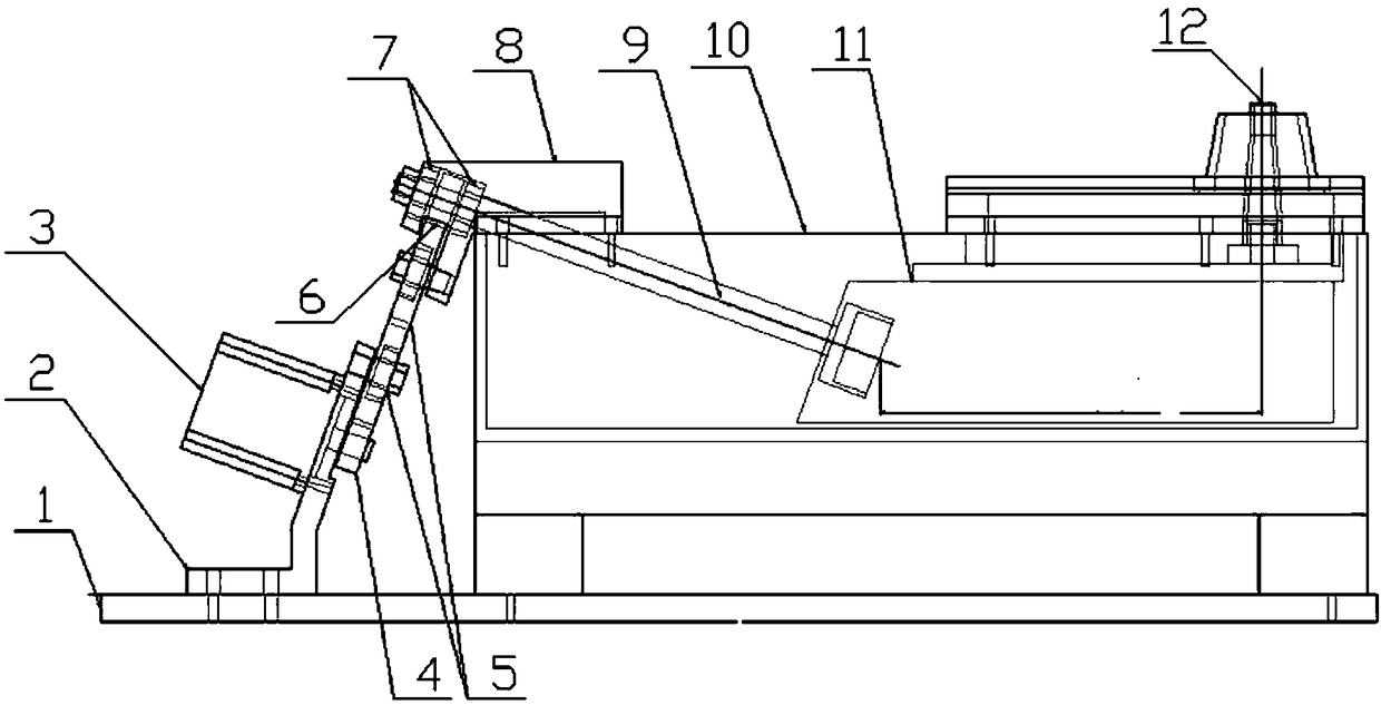
[0029] Such as Figure 1-Figure 2 As shown, the present invention provides an angle gear high temperature tin alloy liquid furnace, including a bottom plate 1, a driving device, a transmission device, an impeller assembly, a runner 11, a driving device mounting seat 2, a tin melting furnace 10 and a soldering tin nozzle 12 ;

[0030] The driving device mounting base 2 is installed on the base plate 1;

[0031] The driving device mounting base 2 is provided with a sloping plate, and the driving device is installed obliquely on the sloping plate;

[0032] The driving device drives the impeller assembly to run through the transmission device;

[0033] The impeller assembly is connected to the tin melting furnace 10 through the flow channel 11;

[0034] The soldering tin nozzle 12 is installed on the tin melting furnace 10;

[0035] The transmission device is a gear transmission device.

[0036] The driving device is a power motor 3 .

[0037] The gear transmission includes ...

Embodiment 2

[0046] Such as Figure 1-Figure 2 As shown, the present invention provides an angle gear high temperature tin alloy liquid furnace, including a bottom plate 1, a driving device, a transmission device, an impeller assembly, a runner 11, a driving device mounting seat 2, a tin melting furnace 10 and a soldering tin nozzle 12 ;

[0047] The driving device mounting base 2 is installed on the base plate 1;

[0048] The driving device mounting base 2 is provided with a sloping plate, and the driving device is installed obliquely on the sloping plate;

[0049] The driving device drives the impeller assembly to run through the transmission device;

[0050] The impeller assembly is connected to the tin melting furnace 10 through the flow channel 11;

[0051] The soldering tin nozzle 12 is installed on the tin melting furnace 10;

[0052] The transmission device is a gear transmission device.

[0053] The driving device is a power motor.

[0054]The gear transmission includes a dr...


PUM


Abstract

The invention relates to an angle gear high-temperature tin alloy liquid furnace. The angle gear high-temperature tin alloy liquid furnace comprises a bottom plate, a driving device, a transmission device, an impeller assembly, a flow passage, a driving device mounting seat, a tin melting furnace and a soldering tin nozzle. The driving device mounting seat is mounted on the bottom plate. The driving device mounting seat is provided with a sloping plate, and the driving device is obliquely mounted on the sloping plate. The driving device drives the impeller assembly to operate through the transmission device. The angle gear high-temperature tin alloy liquid furnace has the beneficial effects that when power is transmitted by gears, line contact is adopted, the contact surface is small, theheat conduction is slowed, the prolonging of the use life of the driving device is facilitated, and the production cost is reduced; and an impeller mounting seat with an angle is installed on the tinmelting furnace to enable an angle to be formed between an impeller and the flow passage and reduce the distance between a tin alloy liquid inlet and the soldering tin nozzle as much as possible, it is beneficial to maintain the temperature of tin alloy liquid to be consistent, reliable and stable temperature parameters are provided for high quality production, and it is ensured that the product quality is not affected by temperature in the production process.

Description

technical field [0001] The invention relates to the field of wave soldering equipment, in particular to an angle gear high-temperature tin alloy liquid furnace. Background technique [0002] At present, the mechanical tin alloy liquid furnaces in the industry all use the motor to drive the impeller to rotate and suck the tin liquid through the belt, and the high-temperature tin liquid is ejected from the nozzle due to the acceleration of the rotation. This kind of technology currently has two obvious defects. 1. When the temperature is too high, the belt will loosen, and the tin liquid will not be ejected smoothly, resulting in a decline in welding quality or the need to replace the belt, which will affect production efficiency. 2. The distance between the impeller and the nozzle opening is relatively large, which can easily cause uneven temperature, and cannot guarantee that the temperature of the tin inhaled by the impeller is consistent with the temperature of the tin at...

Claims


Application Information

Patent Timeline
Patent Type & Authority Applications(China)
IPC IPC(8): B23K1/08B23K3/06
CPCB23K1/085B23K3/0669
Inventor 庞永瑞
Owner 深圳普洲自动化设备有限公司
Learn More