Biomass high molecular material cutting equipment
A technology of polymer materials and cutting equipment, which is applied in metal processing and other directions, can solve the problem that the scraps cannot be absorbed, and achieve the effect of novel design
- Summary
- Abstract
- Description
- Claims
- Application Information
AI Technical Summary
Problems solved by technology
Method used
Image
Examples
Embodiment 1
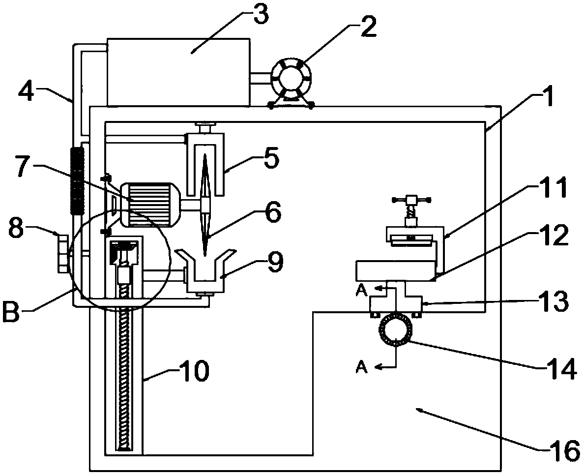
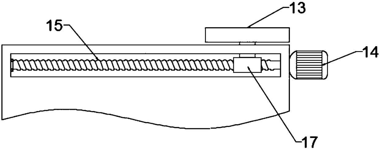
[0025] see figure 1 , 2 , 4 and 5, in the embodiment of the present invention, a kind of biomass polymer material cutting equipment comprises equipment frame 1, chip removing mechanism and cutting motor 7; Said cutting motor 7 is fixed on the inside of equipment frame 1 through motor base, cutting A cutting knife 6 is fixedly installed on the output shaft of the motor 7. When the cutting motor 7 rotates, the cutting knife 6 is driven to rotate, thereby realizing the cutting of the polymer plate. The chip removal mechanism is arranged at the side end of the cutting knife 6. Fan 2, collection cavity 3, upper cover body 5 and ash hopper 9, the lower end of upper cover body 5 is set in opening shape, and is positioned at the upper end of cutting knife 6, and the upper half of cutting knife 6 is positioned at upper cover body 5, The outer wall of the upper cover body 5 is provided with a cavity, the cavity communicates with one end of the collection chamber 3 through the conduit 4...
Embodiment 2
[0032] see figure 1 , 2, 4, 5 and 6, the difference between the second embodiment and the first embodiment is that the placing table 12 is provided with a fixing mechanism, and the fixing mechanism includes an adjusting rod 28, a third threaded rod 29, a third threaded sleeve 30, an abutment Connecting plate 31 and L-shaped plate 32, the inside of said L-shaped plate 32 is provided with abutment plate 31, the upper end of abutment plate 31 is rotatably connected with one end of the third threaded rod 29 through a rotary joint, the other end of the third threaded rod 29 One end passes through the L-shaped plate 32 and is fixedly connected with the adjustment rod 28. The third threaded rod 29 at the upper end of the L-shaped plate 32 is threaded to the outside of the third threaded sleeve 30, and the third threaded sleeve 30 is connected to the L-shaped plate 32. Fixing, the third threaded rod 29 is rotated by the adjusting rod 28, and the third threaded rod 29 can move up and ...
Embodiment 3
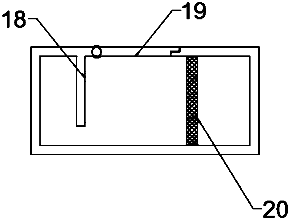
[0034] see Figure 1~5 The difference between embodiment three and embodiment one is that the upper end of the collection chamber 3 is hinged with a dodge door 19, thereby facilitating the cleaning of the collection chamber 3, the inside of the collection chamber 3 is provided with a baffle plate 18, and the upper end of the baffle plate 18 is connected to the The collection chamber 3 is fixed, and there is a gap between the lower end of the baffle plate 18 and the bottom of the collection chamber 3. A screen 20 is also arranged in the collection chamber 3, and the baffle plate 18 provided can effectively prevent the debris from directly impacting the screen 20. The screen 20 causes damage.
PUM
 Abstract
Description
Claims
Application Information
 - R&D
- Intellectual Property
- Life Sciences
- Materials
- Tech Scout
- Unparalleled Data Quality
- Higher Quality Content
- 60% Fewer Hallucinations
Browse by: Latest US Patents, China's latest patents, Technical Efficacy Thesaurus, Application Domain, Technology Topic, Popular Technical Reports.
© 2025 PatSnap. All rights reserved.Legal|Privacy policy|Modern Slavery Act Transparency Statement|Sitemap|About US| Contact US: help@patsnap.com


