
A hybrid transmission system

A hybrid and hybrid drive technology, applied in the automotive field, can solve the problems of complex torque output structure control, and achieve the effects of facilitating space loading, reducing design complexity and simple structure

Active Publication Date: 2019-01-15
GREAT WALL MOTOR CO LTD
View PDF5 Cites 3 Cited by
  • Summary
  • Abstract
  • Description
  • Claims
  • Application Information

AI Technical Summary

Problems solved by technology

[0005] In view of this, the present invention aims to propose a hybrid power transmission system to solve the problems in the hybrid drive mode caused by the double clutch and the structure of the engine, the motor and the complex planetary row adopted in the hybrid power transmission system in the prior art. Next, the torque output structure and control complex issues

Method used


Image

  • A hybrid transmission system
  • A hybrid transmission system

Examples


Embodiment 1

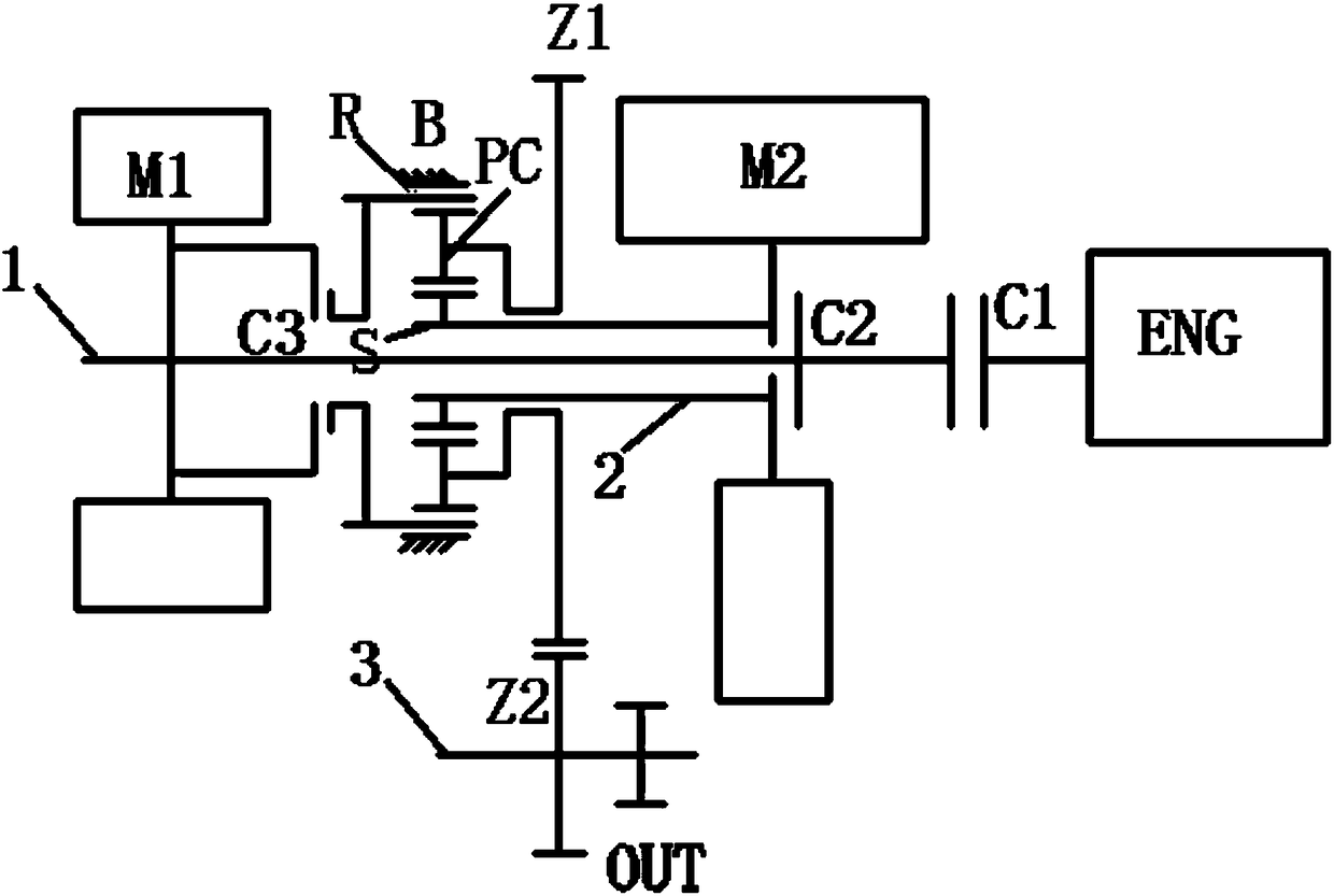
[0024] refer to figure 1 , is a schematic diagram of a hybrid transmission system described in an embodiment of the present invention, and may specifically include:

[0025] engine ENG, first motor M1 and second motor M2, first clutch C1, second clutch C2 and third clutch C3 and first transmission shaft 1, second transmission shaft 2 and third transmission shaft 3, planetary carrier PC, Brake B, first gear Z1 and second gear Z2, ring gear R, sun gear S, power output interface OUT, where:

[0026] The engine ENG is connected to the first clutch C1 through a crankshaft;

[0027] The planet carrier PC is engaged with the ring gear R and the sun gear S respectively to form a planetary row structure;

[0028] The planetary row structure is respectively directly connected with the first gear Z1 to output power;

[0029] The first motor M1 is selectively connected to the ring gear R through the third clutch C3, so as to output electric power to the planetary row structure;

[003...


PUM


Abstract

A hybrid transmission system includes an engine, a first electric machine and a second electric machine, a first clutch, a second clutch and a third clutch, and a first drive shaft, a second drive shaft and a third drive shaft, a planet carrier, a brake, a first gear and a second gear, a ring gear, a sun gear, and a power output interface, wherein the engine is connected to the first clutch through a crankshaft; the planet carrier is meshed and connected with the ring gear and the sun gear respectively to form a planetary row structure; the planetary row structure is directly connected with the first gear and the second gear respectively; the first motor is selectively connected to the ring gear through a third clutch. The second motor rotor is directly connected with the sun gear; a brakeselectively braking the ring gear; the second drive shaft is selectively connectable with the first drive shaft through a second clutch; the power take-off interface is connected to the planetary rowstructure through a third drive shaft. The system solves the problem that the structure of hybrid transmission system is complex and the torque consumed during transmission is too large.

Description

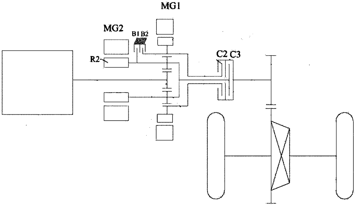
technical field [0001] The invention relates to the field of automobiles, including a hybrid transmission system. Background technique [0002] Due to the increasing energy crisis and air pollution, the state has introduced a series of energy-saving and emission-reduction measures, and introduced stricter emission regulations for the automobile industry, thus promoting the technological progress of hybrid electric vehicles. [0003] In the existing technology, such as figure 1 As shown, the transmission system used in hybrid vehicles usually adopts a simple planetary row, in which the engine is connected to the sun gear, the motor MG1 is connected to the ring gear, and the motor MG2 is connected to the planet carrier. Two clutches C2 and C3, where C2 connects the ring gear and the output end, C3 connects the planet carrier and the output end, two brakes B1 and B2, where B1 brakes the planet carrier, and B2 brakes the ring gear. It can realize pure electric mode, pure engin...

Claims


Application Information

Patent Timeline
Patent Type & Authority Applications(China)
IPC IPC(8): B60K6/365B60K6/547
CPCB60K6/365B60K6/547
Inventor 樊晓磊杜柳絮李洪伟刘永超宋杰
Owner GREAT WALL MOTOR CO LTD
Learn More