High-pressure jet grouting piling device and high-pressure jet grouting piling method with same

A technology of high-pressure rotary grouting pile machine and grouting port, which is applied in the direction of sheet pile wall, foundation structure engineering, construction, etc., which can solve the problems of uneven diffusion of grout, slow diffusion of grout, and inconsistent pile diameters, etc. Uniform diffusion speed, balanced and stable grouting pressure, uniform pile diameter

Pending Publication Date: 2019-01-15
浙江易通特种基础工程股份有限公司
View PDF0 Cites 0 Cited by
  • Summary
  • Abstract
  • Description
  • Claims
  • Application Information

AI Technical Summary

Problems solved by technology

[0004] The high-pressure rotary grouting pile machine and construction method of the prior art have the following defects: first, the geological conditions of actual construction are complex, and the soil layer is soft or hard, so that when rotary spraying in soft soil, the soil resistance is small and the slurry spreads quickly , the pile diameter is large, but in hard soil rotary spraying, the soil resistance is large, the slurry diffuses slowly, and the pile diameter is small. Therefore, the slurry spreads unevenly in the soil with different hardness, and the final pile diameters are inconsistent. The quality of the pile is not ideal; although the grouting pump can increase the grouting pressure to a certain extent, it is found in actual operation that when faced with hard soil, the boosting effect is limited, and the slow diffusion of grout in hard soil cannot be fundamentally solved. , the problem of small pile diameter; secondly, even if there is a certain ability to adjust the spraying pressure, in actual construction, it is necessary to increase or decrease the spraying pressure according to the hardness and thickness of the soil layer in the geotechnical investigation report as an adjustment basis, but The geotechnical survey report is only accurate and effective for the survey location, but there is an objective spatial deviation between the actual drilling location and the survey location, so there are often some changes in the soil layer at the drilling location, and the data at the survey point cannot truly reflect the drilled soil. Therefore, the method of pressure adjustment based on the survey report is cumbersome, laborious, imprecise and has a certain lag

Method used


Image

  • High-pressure jet grouting piling device and high-pressure jet grouting piling method with same
  • High-pressure jet grouting piling device and high-pressure jet grouting piling method with same
  • High-pressure jet grouting piling device and high-pressure jet grouting piling method with same

Examples


Embodiment Construction

[0025] The present invention will be further described below in conjunction with the accompanying drawings and specific embodiments.

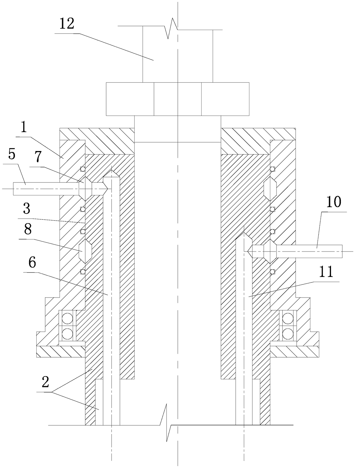
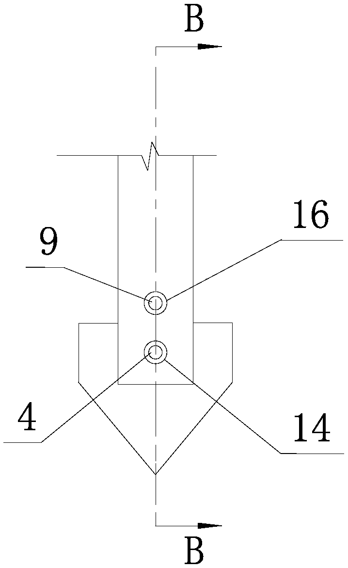
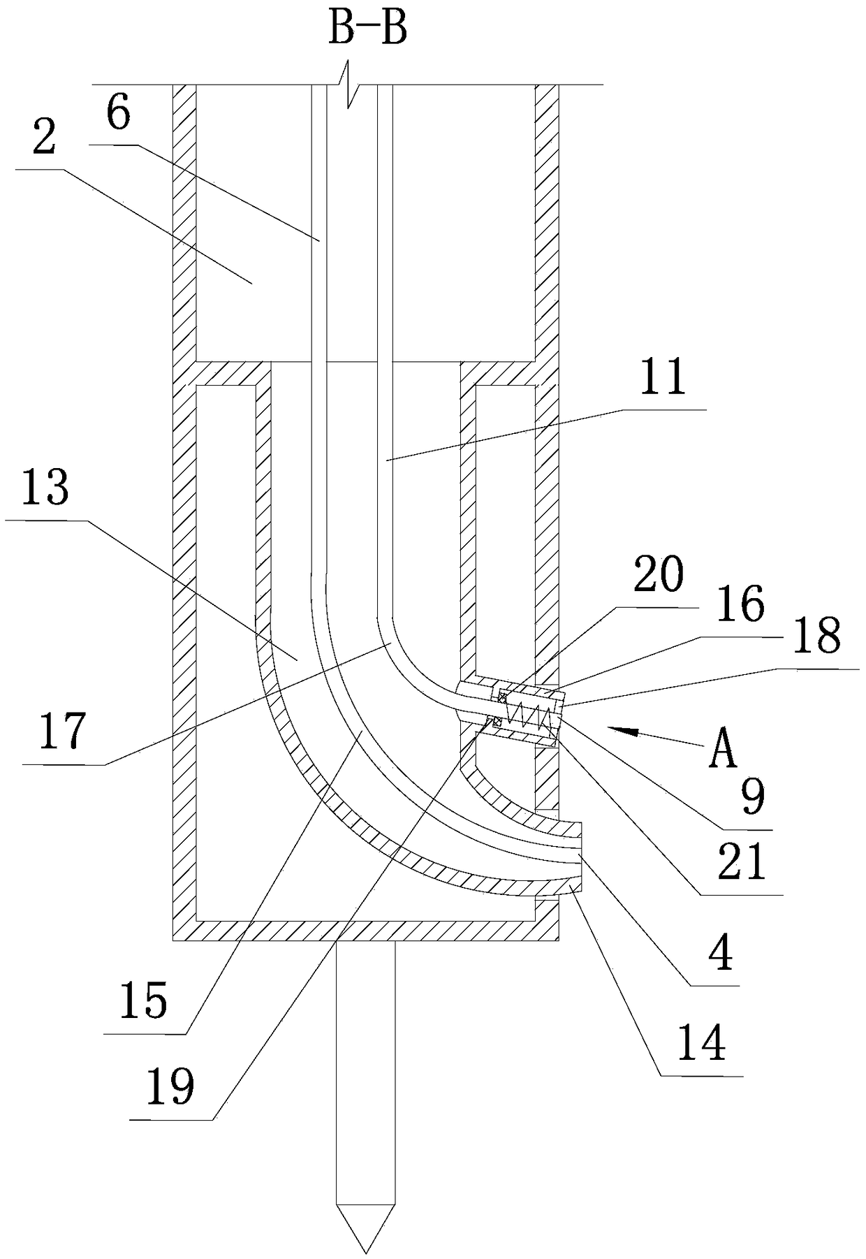
[0026] Such as figure 1 , figure 2 , image 3 , Figure 4 , Figure 5 As shown, the high-pressure rotary grouting pile machine of the present invention includes a power head 1, a drill pipe 2, a drill bit positioned at the lower end of the drill pipe 2, a first grouting pipe communicated with the first grouting pump, and a second grouting pump. The second grouting pipe

[0027] The power head 1 is provided with a cylindrical installation chamber 3. Since the power head 1 is a conventional prior art, only a part of the power head 1 is shown in the accompanying drawings of the application, that is, the installation chamber in the power head 1 3 side wall parts. The upper part of the drill rod 2 is rotatably installed in the installation chamber 3 of the power head 1 through bearings. An upper annular chamber 7 and a lower annular chamber ...


PUM


Abstract

The invention discloses a high-pressure jet grouting piling device and a construction method thereof. The piling device comprise a power head, a drilling rod and first and second grouting pipes, the drilling rod is rotationally installed in an installation cavity of the power head, a drill bit of the drilling rod is provided with a first grouting port, the first grouting pipe comprises a first fixed segmented positioned in the power head and a first rotary segment positioned in the drilling rod, and the first rotary segment is communicated with the first grouting port; upper and lower annularcavities are arranged between the installation cavity and the drilling rod; the first fixed segment is communicated with the first rotary segment via the upper annular cavity; and the second groutingpipe comprises a second fixed segment positioned in the power head and a second rotary segment positioned in the drilling rod, the second fixed segment is communicated with the second rotary segment via the lower annular cavity, and the second rotary segment is communicated with a second grouting port. When the drilling bit is positioned in a hard soil layer, the two grouting pipes inject slurry in double amount simultaneously. Via the piling device and the construction method thereof, it is ensured that the slurry is diffused uniformly by rotary grouting in the soft or hard soil layer.

Description

technical field [0001] The invention relates to foundation treatment technology in the field of civil engineering, in particular to a high-pressure rotary grouting pile driver and a method for constructing high-pressure rotary grouting piles using the pile driver. Background technique [0002] In the prior art, high-pressure jet grouting piles are often used for foundation reinforcement or foundation pit water stop. The construction process of the high-pressure rotary grouting pile is that the high-pressure rotary grouting pile machine is first drilled to the bottom of the hole, and then the drill pipe is pulled out while the cement slurry is sprayed, and the cement slurry sprayed out by the high-pressure rotary spraying is mixed with the soil to form a cement-soil reinforcement. , repeat the above process until the drill pipe is pulled out of the hole. [0003] The high-pressure rotary grouting pile machine of prior art comprises chassis, main mast, power head, hoist, dril...

Claims


Application Information

Patent Timeline
Patent Type & Authority Applications(China)
IPC IPC(8): E02D5/46
CPCE02D5/46
Inventor 徐新战付连红徐斌郑源张陈刘学政
Owner 浙江易通特种基础工程股份有限公司
Why Eureka
Try Eureka