
Communication tower with retractable antennas

A communication tower and antenna technology, which is applied in the field of communication towers, can solve the problems of antenna bending, excessive wind speed, and antenna damage, and achieve the effects of reducing wind resistance, enhancing stability, and avoiding wind deformation

Inactive Publication Date: 2019-01-15
郑州辛西亚信息科技有限公司
View PDF0 Cites 9 Cited by
  • Summary
  • Abstract
  • Description
  • Claims
  • Application Information

AI Technical Summary

Problems solved by technology

[0003] As an important part of the communication tower, the antenna is often installed on the top of the communication tower. However, when encountering strong convective weather, the wind speed is too high, which can easily bend the antenna and cause damage to the antenna

Method used


Image

  • Communication tower with retractable antennas
  • Communication tower with retractable antennas
  • Communication tower with retractable antennas

Examples


Embodiment 1

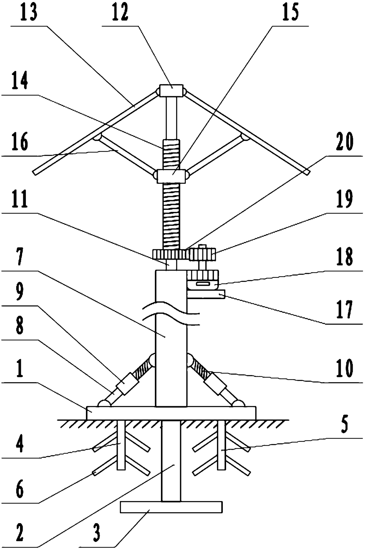
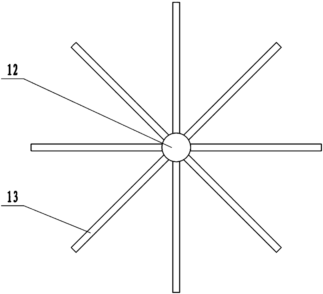
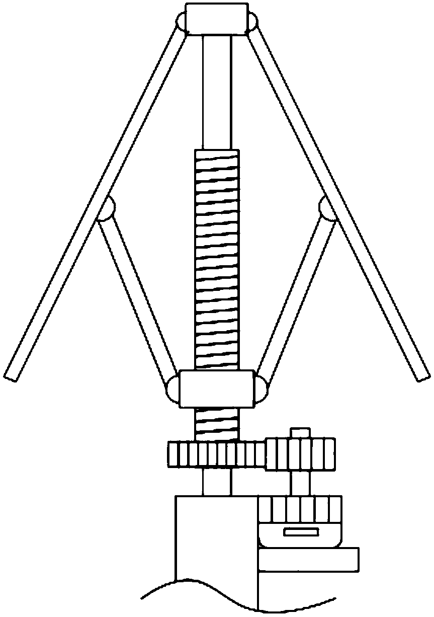
[0021] see Figure 1-3 , in an embodiment of the present invention, a communication tower with a retractable antenna includes a base 1, a tower body 7 and an antenna 13, the bottom of the base 1 is fixedly connected with a fixed pile 2, the fixed pile 2 is buried in the ground, and the fixed pile The lower end of 2 is fixedly connected with a fixed plate 3, and the fixed pile 2 and the fixed plate 3 are used to stabilize the base 1. The upper surface of the base 1 is fixedly connected with a tower body 7, and the side wall of the tower body 7 is hinged with a screw rod 10. The screw rods 10 are annularly distributed around the tower body 7. The free end of the screw rod 10 is covered with a sleeve 9. The sleeve 9 is threadedly connected with the screw rod 10. The lower end of the sleeve 9 is connected with a pull rod 8 and a pull rod 8 in rotation. The lower end of the base is hinged with the base 1, and the sleeve 9 is rotated to form a tension between the pull rod 8 and the ...

Embodiment 2

[0024] On the basis of embodiment 1, the left and right positioning rods 4 and 5 are respectively arranged on the left and right sides of the fixed pile 2, and the left positioning rod 4 and the right positioning rod 5 are fixedly connected with the bottom of the base 1 respectively, and the left positioning rod 4 1. Fixed rods 6 are distributed on the right positioning rod 5, and the stability of the base 1 is further enhanced by using the left positioning rod 4, the right positioning rod 5, and the fixed rods 6.


PUM


Abstract

The invention discloses a communication tower with retractable antennas, which comprises a base, a tower body and antennas. The upper surface of the base is fixed with the tower body; the top of the tower body is fixed with a top rod; the top of the top rod is fixed with a fixing disk; the edge of the fixing disk is hinged with the antennas; the middle of the top rod is sleeved with a sleeve; thesleeve is rotationally connected with the top rod; the middle of the sleeve is sleeved with a slider; the slider is in threaded connection with the sleeve; the middle of each antenna is hinged with aconnecting rod; the lower end of the connecting rod is hinged with the slider; the side wall of the tower body is fixed with a motor bracket; and the upper surface of the motor bracket is fixed with amotor. When windy weather is encountered, the antenna is driven downwardly by the motor, the antenna is retracted, the wind resistance is reduced and the antenna can be prevented from being blown deformed by the wind; after the heavy wind, the motor is controlled to rotate reversely, the antenna rotates upwardly, and the antenna is opened again; and through arranging a fixing pile and a fixing plate at the bottom of the base and by using left positioning rods, right positioning rods and fixing bars, the stability of the base is further enhanced.

Description

technical field [0001] The invention relates to the technical field of communication, in particular to a communication tower with a retractable antenna. Background technique [0002] Communication tower is a kind of signal transmission tower, also called signal transmission tower or signal tower. Its main function is to support signal transmission and support signal transmission antenna. Composed of components, and treated by hot-dip galvanizing, it is mainly used for the transmission and launch of microwave, ultrashort wave, and wireless network signals. Communication tower is also a form of public radio station, which refers to a radio transceiver station that transmits information between mobile phone terminals through a communication switching center in a certain radio coverage area. Since the popularization of wireless cities , The signal tower is also used as the base point for signal transmission of urban WIFI. [0003] As an important part of the communication towe...

Claims


Application Information

Patent Timeline
IPC IPC(8): E04H12/18E04H12/20E04H12/22H01Q1/00H01Q1/08H01Q1/12H01Q1/36
CPCE04H12/18E04H12/20E04H12/2215H01Q1/005H01Q1/08H01Q1/1242H01Q1/36
Inventor 贾振鹏
Owner 郑州辛西亚信息科技有限公司
Learn More