Methods and systems for spark timing control

A technology of spark timing and intake system, applied in spark ignition controller, electrical control, automatic control and other directions, can solve the problem of torque response time reduction, knocking, etc.

Pending Publication Date: 2019-01-15
FORD GLOBAL TECH LLC
View PDF1 Cites 0 Cited by
  • Summary
  • Abstract
  • Description
  • Claims
  • Application Information

AI Technical Summary

Problems solved by technology

Therefore, even after adjusting spark timing based on humidity, it is possible to experience knock due to momentary changes in air charge respo...

Method used


Image

  • Methods and systems for spark timing control
  • Methods and systems for spark timing control
  • Methods and systems for spark timing control

Examples


Embodiment Construction

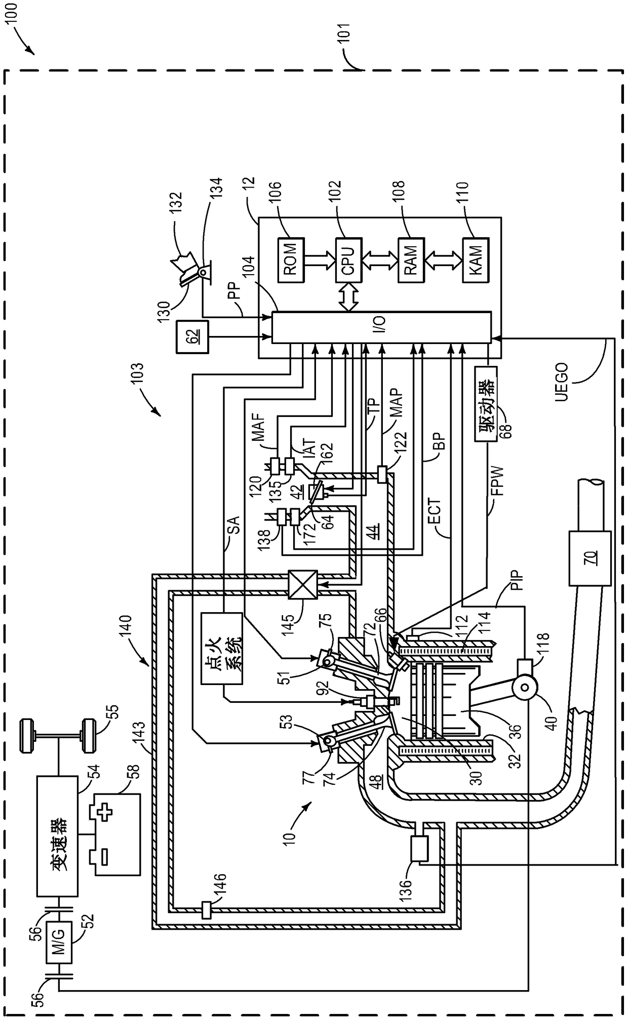
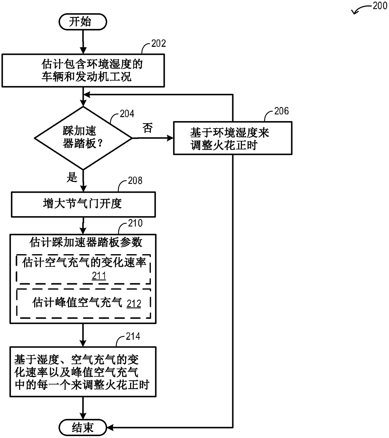
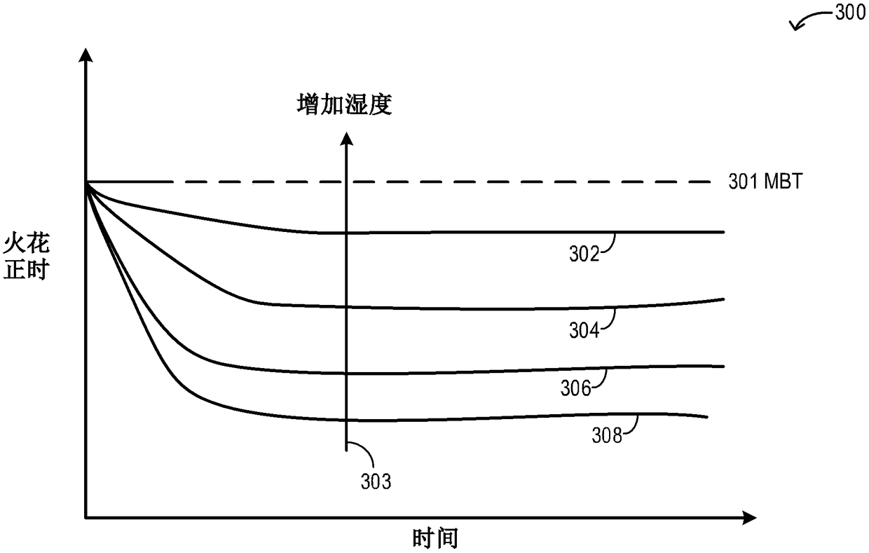
[0017] The following description relates to systems and methods for adjusting spark timing during a tip-in event based on ambient humidity and instantaneous tip-in parameters. An example engine system coupled to a hybrid vehicle is in figure 1 shown in . The engine controller can be configured to execute control routines such as figure 2 Example routine to adjust spark timing during tip-in conditions. Example graphs for adjusting spark timing based on each of humidity, rate of change of air charge, and peak air charge during multiple tip-ins are shown separately at Figure 3A to Figure 3C middle. An example plot with spark timing curves adjusted based on each of humidity, rate of change of air charge, and peak air charge while compensating for synergistic and counterproductive effects is shown at Figure 3D place. Example adjustments to spark timing during a tip-in are shown in Figure 4 middle.

[0018] figure 1 is a schematic diagram illustrating a vehicle system 10...


PUM


Abstract

The application relates to methods and systems for spark timing control, and provides methods and systems are provided for adjusting spark timing based on ambient humidity and transient tip-in parameters. In one example, a method may include, during a tip-in, retarding spark timing based on each of ambient humidity, peak air charge, and rate of change of air charge. As such, the spark timing retard may be higher at lower humidity levels, and the spark timing retard may be lower at higher humidity levels.

Description

technical field [0001] The present invention generally relates to methods and systems for controlling a vehicle engine to adjust spark timing based on ambient humidity and tip-in parameters. Background technique [0002] Combustion in engine cylinders can be affected by ambient humidity. Spark-ignited internal combustion engines may experience undesired combustion events, such as detonation, during low humidity conditions where the combustion rate may increase. During higher humidity conditions, if the engine does not account for the diluent content in the air-fuel mixture, water in the charge air may act as a diluent and the burn rate may decrease, resulting in reduced engine efficiency. [0003] Various methods are provided to compensate for ambient humidity in order to improve combustion stability and engine efficiency. In one example, as shown in US20140109870 to Glugla et al., it is taught to adjust spark timing based on ambient humidity and condensate level in the ch...

Claims


Application Information

Patent Timeline
IPC IPC(8): F02P5/15
CPCF02P5/1502F02D11/10F02D11/106F02D37/02F02D41/045F02D41/18F02D2200/0414F02D2200/0418F02D2200/602F02D2200/703F02P5/045F02P5/1504Y02T10/40
Inventor C·P·格鲁格拉M·哈基姆
Owner FORD GLOBAL TECH LLC
Why Eureka
Try Eureka