Thrust plate assembly for turbo compressor

A technology of a turbo compressor and a thrust plate is applied to the components, pump elements, mechanical equipment and other directions of a pumping device for elastic fluids, which can solve the problems of easy wear and loosening of the thrust plate, and achieve the advantages of not easy to loosen, Ensure the accuracy of positioning and facilitate the effect of fixing

Pending Publication Date: 2019-01-15
四川聚亿重工有限公司
View PDF9 Cites 0 Cited by
  • Summary
  • Abstract
  • Description
  • Claims
  • Application Information

AI Technical Summary

Problems solved by technology

[0007] In order to solve the above technical problems, the present invention proposes a thrust plate assembly of a turbocompressor, which can effectively solve the problem that the thrust plate is easy to wear and loosen in the prior art, can improve the assembly efficiency of the thrust plate assembly, and extend the length of the thrust plate. Component life

Method used


Image

  • Thrust plate assembly for turbo compressor

Examples


Embodiment 1

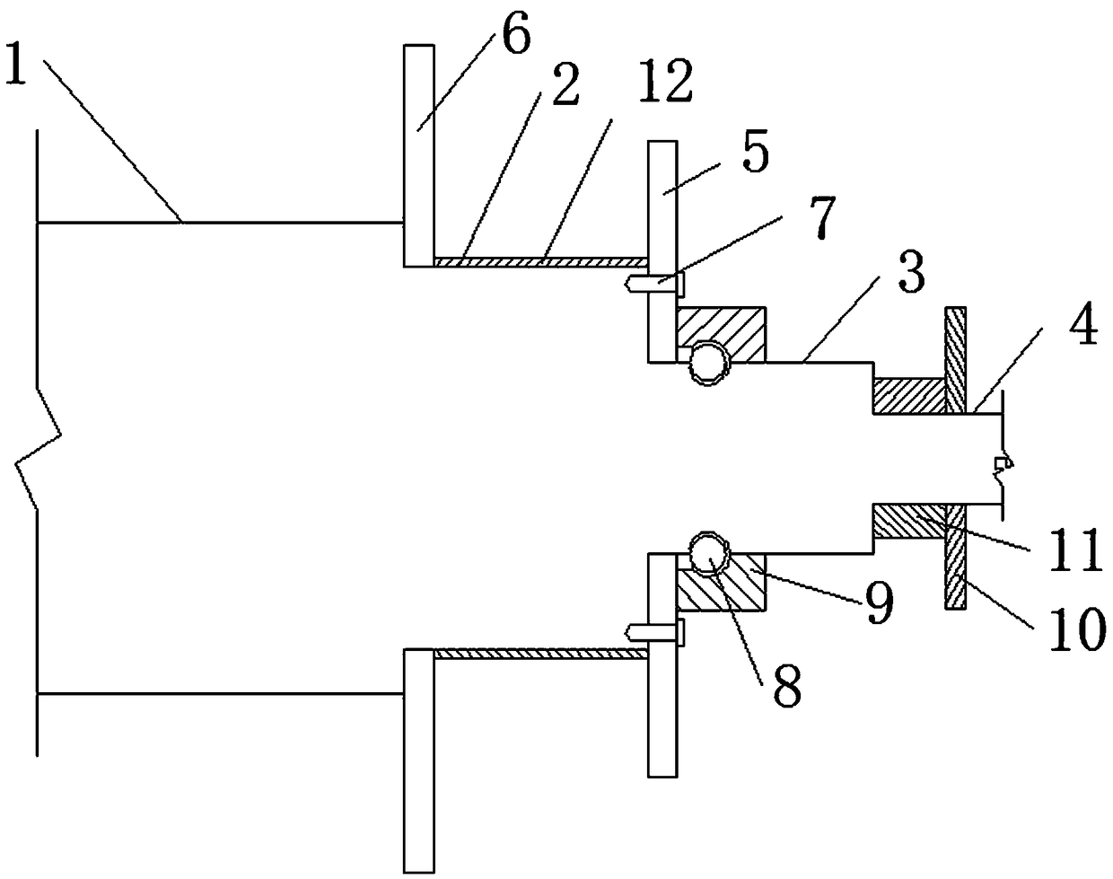
[0032] As the basic embodiment of the present invention, the present invention includes a thrust plate assembly of a turbocompressor, including a thrust plate and a rotating shaft, and the rotating shaft is a stepped shaft, including a first-stage shaft 1, a second-stage shaft 2, and a third-stage shaft 3 and the fourth-stage shaft 4, the thrust plate includes a main thrust plate 5 and an auxiliary thrust plate 6, the auxiliary thrust plate 6 is located on the second-stage shaft 2, and the auxiliary thrust plate 6 is integrally formed with the rotating shaft; the main thrust plate The thrust plate 5 is located on the third-stage shaft 3, and the main thrust plate 5 is provided with several through holes, and the screws 7 pass through the through holes on the main thrust plate 5 to fix the main thrust plate 5 and the rotating shaft; the third-stage shaft 3 is also provided with a positioning collar 8 and an annular retaining ring 9 abutting against the positioning collar 8. The ...

Embodiment 2

[0034] As a preferred embodiment of the present invention, the present invention includes a thrust plate assembly of a turbocompressor, including a thrust plate and a rotating shaft, and the rotating shaft is a stepped shaft, including a first-stage shaft 1, a second-stage shaft 2, a third-stage shaft Shaft 3 and fourth-stage shaft 4, the thrust disc includes a main thrust disc 5 and an auxiliary thrust disc 6, the auxiliary thrust disc 6 is located on the second-stage shaft 2, and the auxiliary thrust disc 6 is integrally formed with the rotating shaft; The main thrust plate 5 is located on the third-stage shaft 3, and the main thrust plate 5 is provided with a number of through holes, and the screws 7 pass through the through holes on the main thrust plate 5 to fix the main thrust plate 5 and the rotating shaft; The step shaft 3 is also provided with a positioning collar 8 and an annular retaining ring 9 abutting against the positioning collar 8. The annular retaining ring 9 ...

Embodiment 3

[0039] As another preferred embodiment of the present invention, the present invention includes a thrust plate assembly of a turbocompressor, including a thrust plate and a rotating shaft, and the rotating shaft is a stepped shaft, including a first-stage shaft 1, a second-stage shaft 2, a third-stage shaft The stage shaft 3 and the fourth stage shaft 4, the thrust plate includes a main thrust plate 5 and an auxiliary thrust plate 6, the auxiliary thrust plate 6 is located on the second stage shaft 2, and the auxiliary thrust plate 6 is integrally formed with the rotating shaft; The main thrust plate 5 is located on the third-stage shaft 3, and the main thrust plate 5 is provided with a number of through holes, and the screws 7 pass through the through holes on the main thrust plate 5 to fix the main thrust plate 5 with the rotating shaft; The third-stage shaft 3 is also provided with a positioning collar 8 and an annular retaining ring 9 abutting against the positioning collar...


PUM


Abstract

The present invention relates to a turbo compressor, and more particularly to a thrust plate assembly for a turbo compressor. The thrust disk assembly comprises a thrust plate and a rotating shaft, wherein the rotating shaft is a stepped shaft including a first stepped shaft, a second stepped shaft, and a third stepped shaft and a fourth stepped shaft. The thrust plate includes a main thrust plateand a secondary thrust plate, wherein the auxiliary thrust plate is located on the second stepped shaft, and the auxiliary thrust plate is integrally formed with the rotating shaft; the main thrust plate is located on the third stepped shaft and fixed with the rotating shaft through a screw, the third stepped shaft is further provided with a positioning collar, an annular retaining ring abuttingagainst the positioning collar, and the fourth stepped shaft is sleeved with a bearing. The thrust disc assembly can effectively solve the problem that the thrust plate is easy to wear and loose in the prior art. The assembly efficiency of a thrust plate assembly is improved, and the service life of the thrust plate assembly is prolonged.

Description

technical field [0001] The invention relates to a turbocompressor, in particular to a thrust disc assembly of a turbocompressor. Background technique [0002] The front and rear thrust plates of the turbo compressor are installed on the main shaft in the form of transition fit and are connected by keys. The installation and removal of the thrust plates is extremely inconvenient, and the contact surface between the thrust plate and the main shaft is easy to be damaged during installation and disassembly. , resulting in the scrapping of parts. If the front and rear thrust discs are connected to the main shaft by interference fit, the thrust discs need to be shrunk, which will easily lead to deformation of the thrust discs and fail to ensure the flatness of the thrust discs. If the front and rear thrust discs are connected to the main shaft with clearance fit, it is easy to cause the thrust discs to shake on the main shaft and increase the shaft vibration of the rotor. [000...

Claims


Application Information

Patent Timeline
Patent Type & Authority Applications(China)
IPC IPC(8): F04D29/051F04D29/056F04D29/053F04D29/05
CPCF04D29/05F04D29/051F04D29/053F04D29/056
Inventor 王小龙白永贵赵成
Owner 四川聚亿重工有限公司
Why Eureka
Try Eureka