Electronic component hardness detection device

A technology for electronic components and testing devices, applied in measuring devices, testing material hardness, instruments, etc., can solve problems such as waste of manpower, deviations, omissions, etc.

Active Publication Date: 2019-01-15
东莞市中证通检测技术有限公司
View PDF19 Cites 1 Cited by
  • Summary
  • Abstract
  • Description
  • Claims
  • Application Information

AI Technical Summary

Problems solved by technology

[0004] In order to overcome the shortcomings of omissions, deviations, and waste of a lot of manpower in manual one-by-one testing, the technical problem of the present invention is: to provide a hardness testing device for electronic components that can replace manual work, is easy to use, and has a low omission rate

Method used


Image

  • Electronic component hardness detection device
  • Electronic component hardness detection device
  • Electronic component hardness detection device

Examples


Embodiment 1

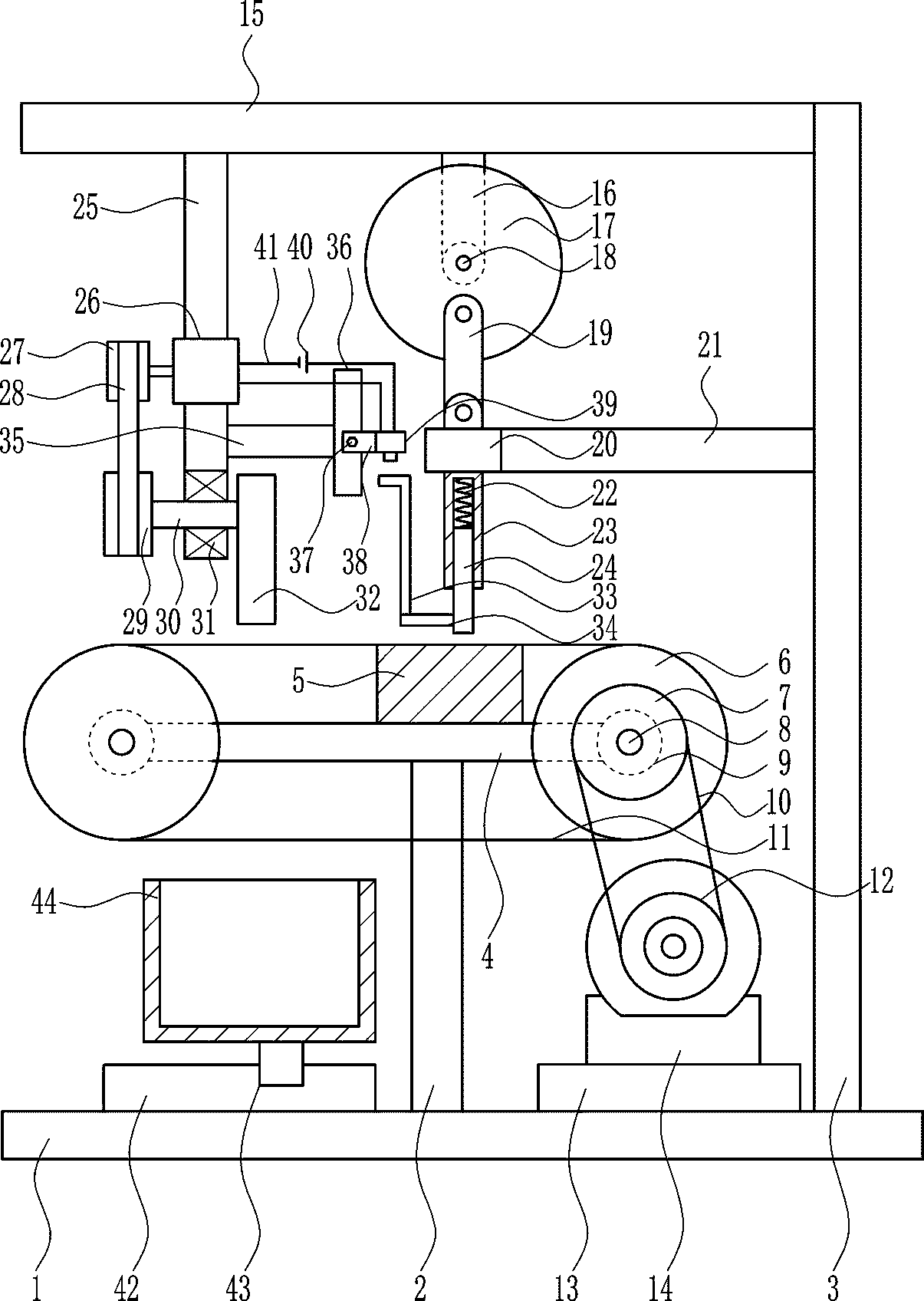
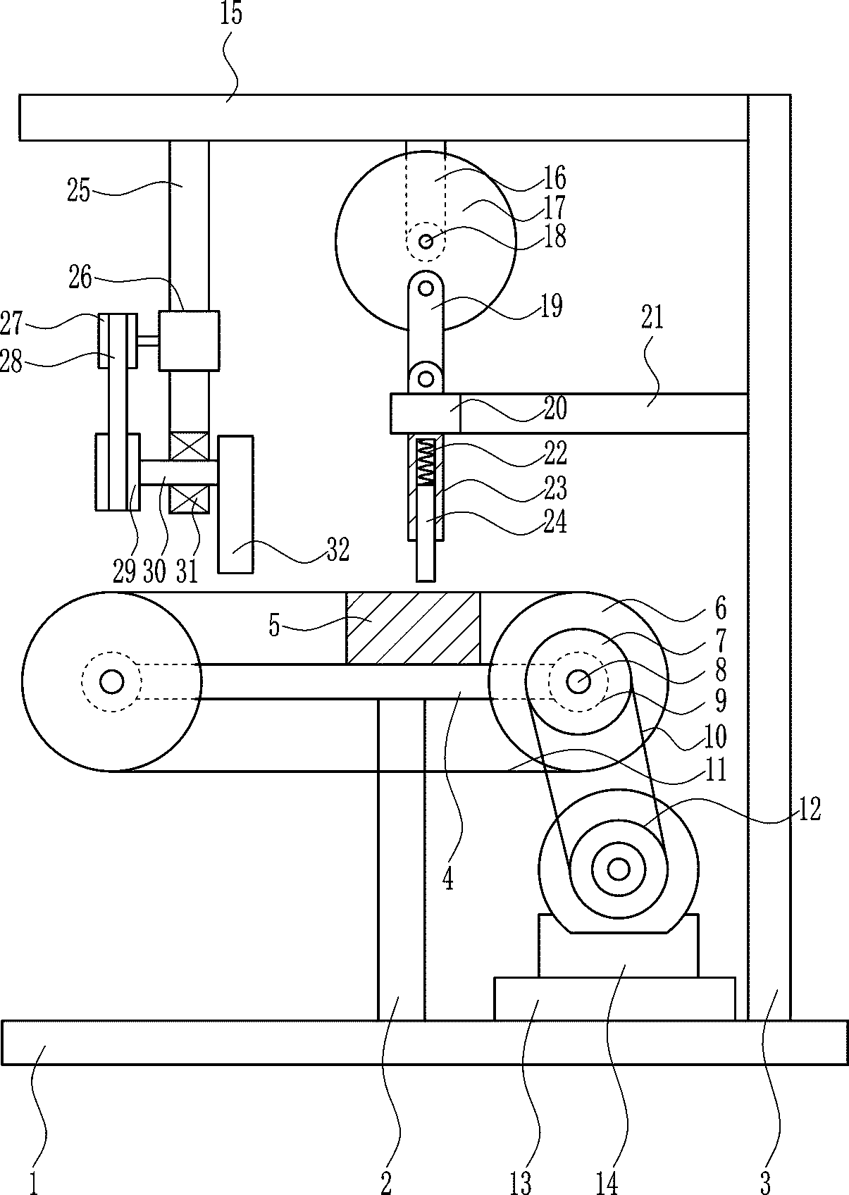
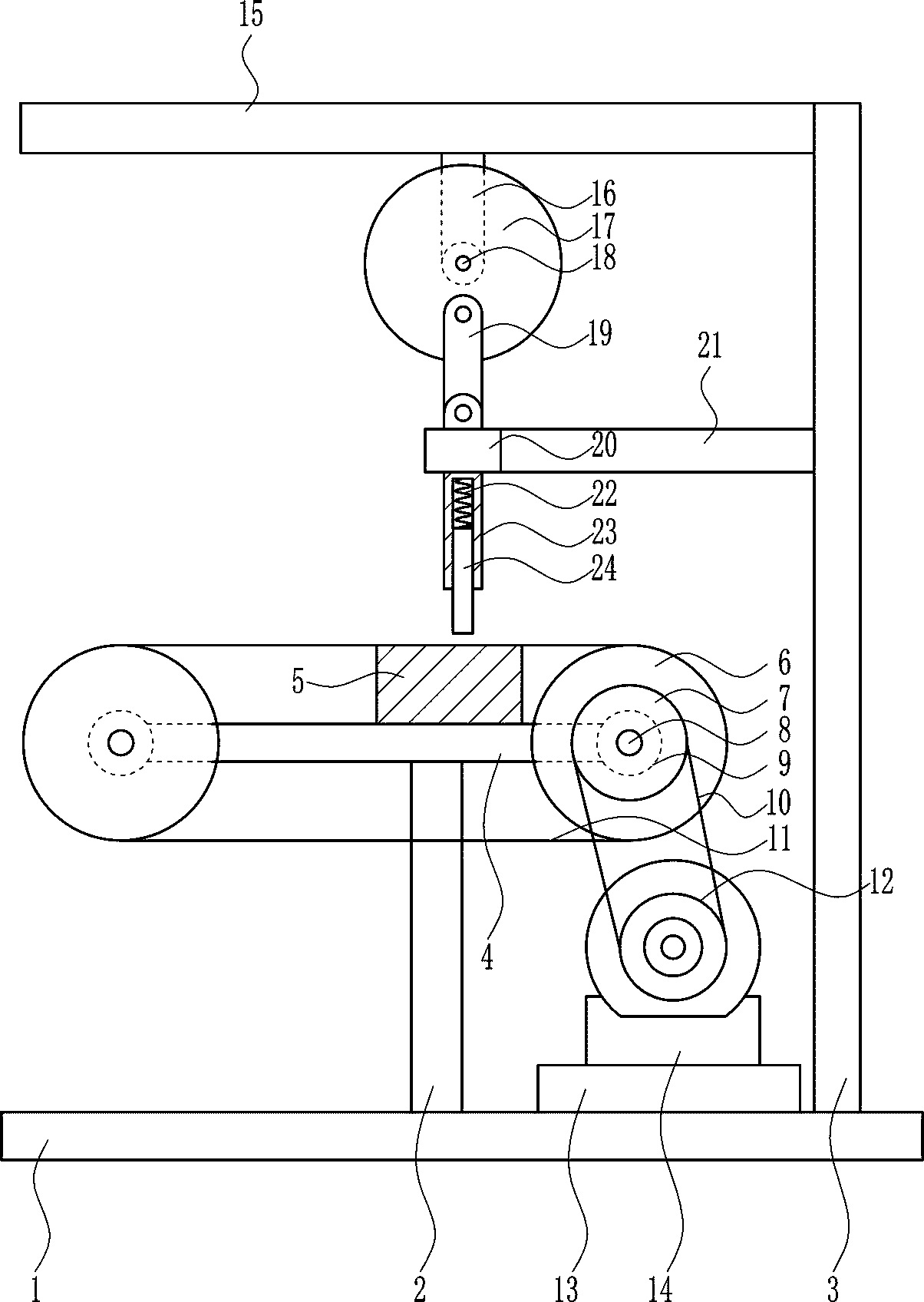
[0024] A device for testing hardness of electronic components, such as Figure 1-5 As shown, it includes a base 1, a first support rod 2, a second support rod 3, a third support rod 4, a pad 5, a transmission wheel 6, a first pulley 7, a first rotating shaft 8, a first bearing 9, a first One connecting belt 10, conveyor belt 11, second pulley 12, support platform 13, first motor 14, fourth support rod 15, fifth support rod 16, turntable 17, second motor 18, first connecting rod 19, sliding sleeve 20. The sixth support rod 21, the first spring 22, the second connecting rod 23 and the sliding rod 24. The upper part of the base 1 is sequentially installed with the first support rod 2, the support platform 13 and the second support rod 3 from left to right. A third support rod 4 is installed on the upper part of a support rod 2, and the third support rod 4 is symmetrically installed with a first bearing 9, and a first rotating shaft 8 is installed in the first bearing 9 through an...

Embodiment 2

[0026] A device for testing hardness of electronic components, such as Figure 1-5As shown, it includes a base 1, a first support rod 2, a second support rod 3, a third support rod 4, a pad 5, a transmission wheel 6, a first pulley 7, a first rotating shaft 8, a first bearing 9, a first One connecting belt 10, conveyor belt 11, second pulley 12, support platform 13, first motor 14, fourth support rod 15, fifth support rod 16, turntable 17, second motor 18, first connecting rod 19, sliding sleeve 20. The sixth support rod 21, the first spring 22, the second connecting rod 23 and the sliding rod 24. The upper part of the base 1 is sequentially installed with the first support rod 2, the support platform 13 and the second support rod 3 from left to right. A third support rod 4 is installed on the upper part of a support rod 2, and the third support rod 4 is symmetrically installed with a first bearing 9, and a first rotating shaft 8 is installed in the first bearing 9 through an ...

Embodiment 3

[0029] A device for testing hardness of electronic components, such as Figure 1-5 As shown, it includes a base 1, a first support rod 2, a second support rod 3, a third support rod 4, a pad 5, a transmission wheel 6, a first pulley 7, a first rotating shaft 8, a first bearing 9, a first One connecting belt 10, conveyor belt 11, second pulley 12, support platform 13, first motor 14, fourth support rod 15, fifth support rod 16, turntable 17, second motor 18, first connecting rod 19, sliding sleeve 20. The sixth support rod 21, the first spring 22, the second connecting rod 23 and the sliding rod 24. The upper part of the base 1 is sequentially installed with the first support rod 2, the support platform 13 and the second support rod 3 from left to right. A third support rod 4 is installed on the upper part of a support rod 2, and the third support rod 4 is symmetrically installed with a first bearing 9, and a first rotating shaft 8 is installed in the first bearing 9 through an...


PUM


Abstract

The invention relates to a hardness detection device, in particular to an electronic component hardness detection device. For solving the technical problem, the electronic component hardness detectiondevice which can replace manual work and is convenient to use and low in omission rate is provided. According to the technical scheme, the electronic component hardness detection device comprises a base, a first supporting rod, a second supporting rod, a third supporting rod, a cushion block, a conveying wheel, a first belt wheel, a first rotating shaft, a first bearing and the like; the first supporting rod, a supporting table and the second supporting rod are sequentially installed at the upper part of the base from left to right; and the third supporting rod is installed at the upper partof the first supporting rod. The device achieves the effects that the manual work can be replaced, the use is convenient, and the omission rate is low; the device can be used to rapidly complete the hardness detection work of a large number of electronic components, so that the detection efficiency is high, the practicability is high, the working load of workers is reduced, the product quality isimproved, and higher economic benefits are provided for factories; and besides, the device is long in service life.

Description

technical field [0001] The invention relates to a hardness testing device, in particular to a hardness testing device for electronic components. Background technique [0002] Electronic components are components of electronic components and small electrical machines and instruments. They are often composed of several parts and can be used in similar products; they often refer to certain parts in industries such as electrical appliances, radios, and instruments, such as capacitors and transistors. The general term for sub-devices such as hairsprings, hairsprings, etc., common ones include diodes, etc. Electronic components include: resistors, capacitors, potentiometers, electron tubes, radiators, electromechanical components, connectors, semiconductor discrete devices, electroacoustic devices, laser devices, electronic display devices, optoelectronic devices, sensors, power supplies, switches, micro-motors , electronic transformers, relays, printed circuit boards, integrated...

Claims


Application Information

Patent Timeline
Patent Type & Authority Applications(China)
IPC IPC(8): G01N3/42
CPCG01N3/42G01N2203/0019G01N2203/0076
Inventor 廖淼帆
Owner 东莞市中证通检测技术有限公司
Why Eureka
Try Eureka