Method and device for non-destructive testing of pavement quality by radar

A non-destructive testing and radar technology, used in radio wave measurement systems, measurement devices, and radio wave reflection/re-radiation, etc. Destruction and other problems, to achieve the effect of improving detection efficiency and detection accuracy, significant social and environmental benefits, and shock absorption protection

Active Publication Date: 2019-01-15
CHONGQING CONSTR RESIDENTIAL ENG +2
View PDF5 Cites 3 Cited by
  • Summary
  • Abstract
  • Description
  • Claims
  • Application Information

AI Technical Summary

Problems solved by technology

In severe cases, water causes corrosion of steel box girders, resulting in structural damage to bridges, leading to major safety accidents
At the same time, the pavement layer of the steel bridge cannot be fully rolled by a road roller like the asphalt pavement of ordinary highways, so the thickness and compaction of the pavement layer cannot be fully guaranteed. The compactness of the pavement layer is insufficient and the strength is too low. Water damage and rutting are prone to occur under climatic conditions; therefore, the detection of physical indicators during the construction of the steel bridge pavement and the detection of diseases during operation is particularly important; at the same time, if the bottom-penetrating radar is better equipped, it will also play a key role in the measurement

Method used


Image

  • Method and device for non-destructive testing of pavement quality by radar
  • Method and device for non-destructive testing of pavement quality by radar
  • Method and device for non-destructive testing of pavement quality by radar

Examples


Embodiment Construction

[0014] In order to make the technical means, creative features, goals and functions achieved by the present invention clearer and easier to understand, the present invention will be further elaborated below in conjunction with the accompanying drawings and specific embodiments:

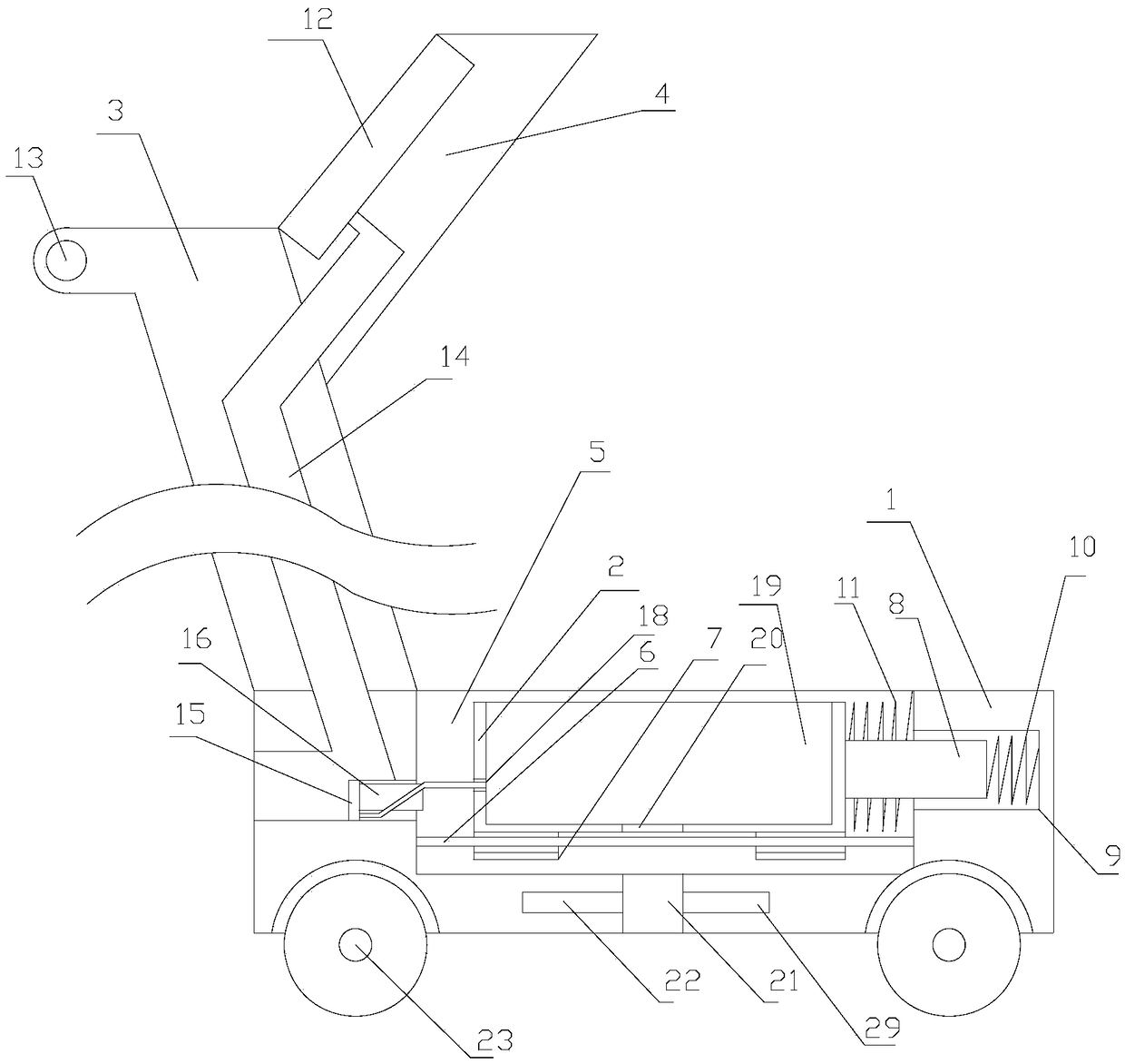
[0015] It should be noted that the up, down, left, and right mentioned in the present invention are attached figure 1 Up and down and left and right are shown.

[0016] The present invention proposes a method for radar non-destructive detection of road surface quality, comprising the following steps,

[0017] 1. The dielectric constant of the pavement layer is determined by the total reflection method, and the thickness of the pavement layer is calculated and verified based on the time history method; the ground-penetrating radar antenna is used, and the ground-penetrating radar antenna includes a transmitting antenna and a receiving antenna. Layer transmits signals, captures weak reflection signals ...


PUM


Abstract

The invention provides a method and a device for non-destructive testing of pavement quality by a radar. The method comprises the following steps of (1) determining a dielectric coefficient of a pavement through a full reflection method; (2) determining a number of the factor in a corresponding void ratio range; (3) creating an FDTD model of a steel bridge pavement, and performing comparative analysis on the FDTD model and a waveform chart of actual pavement radar reflection wave; (4) detecting a slide and emptying part of the steel bridge pavement; and (5) making control measures for qualityproblems such as pavement thickness, compactness, bottom slip and emptying. The method measures thickness of the steel bridge pavement scientifically according to pavement radar, determines an impactfactor mu of a corresponding shape according to different void ratio ranges, so as to improve measurement accuracy of compactness, and realizes non-destructive test of cracks of the steel bridge pavement and bottom slip and emptying disease. The device for non-destructive testing of pavement quality by a radar is convenient to install a bottom inspection radar and an operation table, and facilitates data detection.

Description

technical field [0001] The invention relates to the field of steel bridge pavement detection, in particular to a method and equipment for radar non-destructive detection of road surface quality. Background technique [0002] Steel bridge deck pavement is different from general road asphalt concrete pavement. It is directly laid on the deck of orthotropic steel bridge. Due to the large flexibility of the deck of orthotropic steel bridge, under the load of heavy vehicles, the The local deformation of the face plate is large and complex, and there are obvious stress concentrations at the joints between the stiffeners and the steel bridge plate and the connection between the diaphragm and the steel bridge plate, which leads to complex and harsh stress on the pavement layer, resulting in various Vertical and horizontal cracks, after the cracks penetrate, surface water enters the interior of the pavement layer, resulting in the failure of the interlayer cohesive force, causing the...

Claims


Application Information

Patent Timeline
Patent Type & Authority Applications(China)
IPC IPC(8): G01S13/88G01S7/41G06F17/50
CPCG01S7/412G01S13/885G06F30/20
Inventor 陈怡宏凌天清颜世福崔立龙张意徐可何敏伍任雄
Owner CHONGQING CONSTR RESIDENTIAL ENG
Why Eureka
Try Eureka