A smart fish feeder

An intelligent, rotating column technology, applied in fish farming, application, climate change adaptation, etc., can solve the problems of difficulty in controlling the amount of fish food, difficult to meet the needs of fish at different times, and inability to store a variety of fish food.

Active Publication Date: 2020-12-29
嘉兴琦玥装饰材料有限公司
View PDF8 Cites 0 Cited by
  • Summary
  • Abstract
  • Description
  • Claims
  • Application Information

AI Technical Summary

Problems solved by technology

[0004] The above patents cannot store a variety of fish food, and it is difficult to meet the needs of fish at different times; and it is difficult to control the amount of fish food fed

Method used


Image

  • A smart fish feeder
  • A smart fish feeder
  • A smart fish feeder

Examples


Embodiment 1

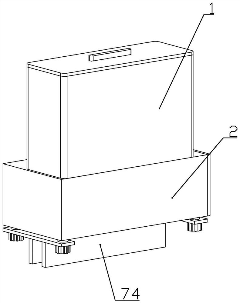
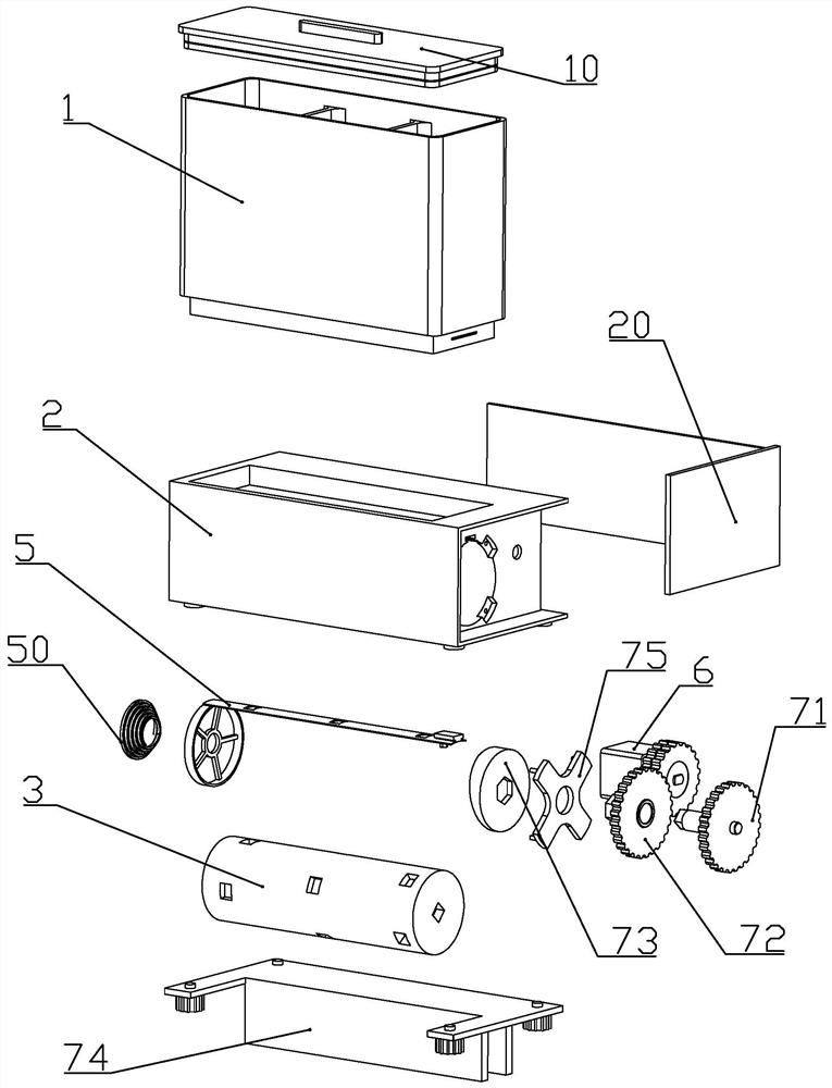
[0050]according toFigure 1 to Figure 13 As shown, the intelligent fish feeder described in this embodiment includes a base 2 and a feed box 1 mounted on the upper end of the base, and a feed box cover 10 is detachably and sealedly connected to the feed box; A plurality of storage cavities 11 for storing fish food are formed in the box; different kinds of granular feed can be stored in each storage cavity, which is convenient to provide different kinds of nutrition for the fish.

[0051]The front part of the base is a column mounting groove 22 with the axis in the horizontal direction; the base is located on one side of the column mounting groove is a gear mounting groove 23, and the base is located at the rear end of the column mounting groove for motor mounting Slot 24.

[0052]The lower end of each storage cavity is formed with a blanking pipe 13 communicating with the top of the rotating column installation groove.

[0053]The inner bottom section of the storage cavity is set in a trapezo...

Embodiment 2

[0100]according toFigure 14 to Figure 17As shown, this embodiment has made the following improvements on the basis of embodiment 1: the lower end of the base is equipped with a foam shell 81 whose lower part extends below the water surface of the fish tank; the foam shell includes a foam shell directly below the discharge channel The foam tank 813 is formed on the foam connecting plate 811 fixedly connected to the base frame at the upper end of the foam tank, and a driving groove 812 located on one side of the foam tank; the upper part of the driving tank is connected to the rotating The column gear is directly opposite.

[0101]A foam discharge port 819 is formed at the lower end of the side wall of the foam tank; the lower part of the side wall of the foam tank is located above the foam discharge port and is rotatably connected with a baffle 88 capable of shielding the foam discharge port.

[0102]A baffle positioning magnet 810 is fixedly connected to the front of the lower end of the ...


PUM


Abstract

The invention discloses an intelligent fishing feeding device. The intelligent fishing feeding device comprises a base and a feed box, and multiple storage cavities for storing fish food are formed inthe feed box. Feed falling tubes are formed at the lower ends of all the storage cavities; a rotating column is rotationally installed in the base, and multiple storage grooves with different depthsare formed in the outer wall of the rotating column; a valve sheet is slidingly connected in the base in the axial direction of the rotating column, and through openings are formed in the valve sheet;discharging channels capable of connecting with all the storage grooves and a fish tank are formed in the lower end of the base; a motor capable of driving the rotating column to rotate or driving the valve sheet to move is installed in the base. The multiple storage cavities are formed and can store multiple kinds of fish food, and different kinds of nutrients are conveniently provided; the multiple storage grooves with different depths are formed, and thus the fish food amount of fish feeding is controlled. According to the intelligent fishing feeding device, feed selection and controllingof the feeding amount are achieved through the single stepping motor; the motor is controlled to forward, rotation of the rotating column is achieved, feed at the specifies position can be fed; the motor is controlled to backward, reciprocating motion of the valve sheet is achieved, and the feed falling process is achieved.

Description

Technical field[0001]The invention belongs to the technical field of pet products, and specifically relates to an intelligent fish feeder.Background technique[0002]The Chinese patent document with the document number CN105746413A discloses a fish feeder, which is characterized in that: the fish feeder includes a storage box, a control device and a timing device, and the control device can control the rotation of the storage box. The device can regularly control the rotation of the storage box through the control device, and the fish feeder can control the rotation of the storage box through the control device. The food in the storage box is scattered into the fish farming area during the rotation, making the fish feeding operation very convenient. Convenient and simple. The rotation time of the storage box can be set through the timing device, so that the storage box can be rotated regularly, which is convenient for automatic feeding every day. The user does not have to worry about ...

Claims


Application Information

Patent Timeline
Patent Type & Authority Patents(China)
IPC IPC(8): A01K61/80
CPCA01K61/80Y02A40/81
Inventor 麻景峰
Owner 嘉兴琦玥装饰材料有限公司
Why Eureka
Try Eureka