
Hydraulic gas compression purification system and compression purification method thereof

A gas compression and purification system technology, applied in chemical instruments and methods, separation methods, dispersed particle separation, etc., can solve the problems of large flow changes and unseen problems, and achieve strict control logic, ingenious design, and broad application prospects Effect

Pending Publication Date: 2019-01-18
克拉玛依九工环保技术有限公司
View PDF0 Cites 0 Cited by
  • Summary
  • Abstract
  • Description
  • Claims
  • Application Information

AI Technical Summary

Problems solved by technology

[0003] So far, there have been no relevant reports on compression purification systems and methods that can compress and purify various gases such as gases containing solid impurities, large flow changes, and hazardous substances.

Method used


Image

  • Hydraulic gas compression purification system and compression purification method thereof
  • Hydraulic gas compression purification system and compression purification method thereof

Examples


Embodiment 1

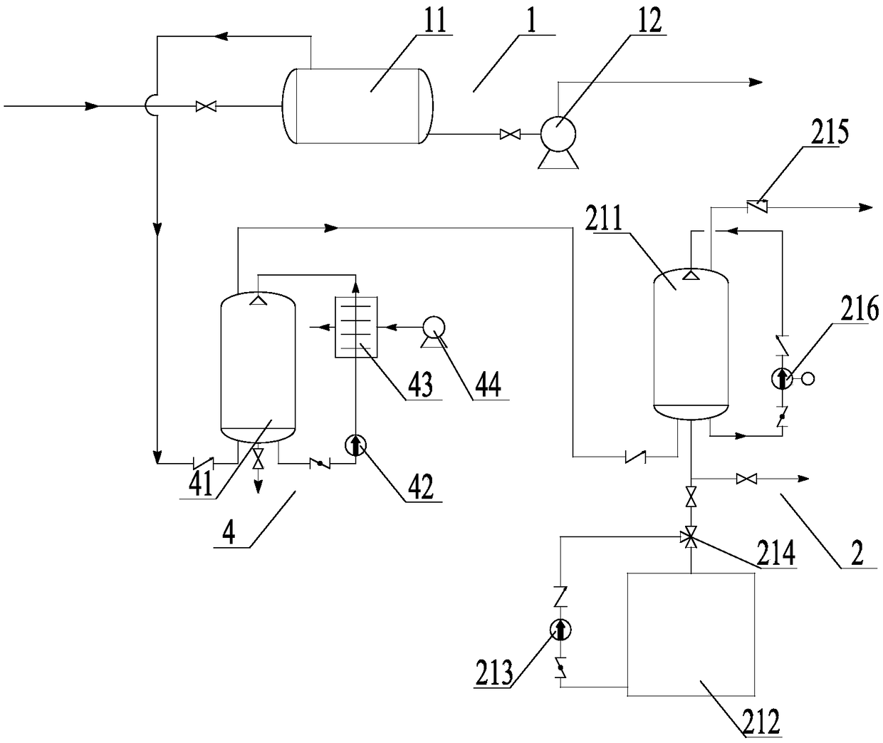
[0047] Such as figure 1As shown, Embodiment 1 of the present invention provides a hydraulic gas compression and purification system, including: a gas-liquid separation assembly 1 , a purification compression assembly 2 , an automatic control assembly and a cooling separation system 4 .

[0048] The gas-liquid separation assembly 1 is used to carry out gas-liquid separation treatment on the incoming liquid containing gas, and the gas outlet end of the gas-liquid separation assembly 1 is connected to the inlet end of the cooling separation system 4 through a pipeline; the cooling separation system 4 For removing liquid droplets and steam in the gas, the outlet end of the cooling separation system 4 is connected to the inlet end of the purification compression assembly 2 through a pipeline; the purification compression assembly 2 is used for compressing and purifying the gas; the The automatic control component is electrically connected with the gas-liquid separation component 1 ...

Embodiment 2

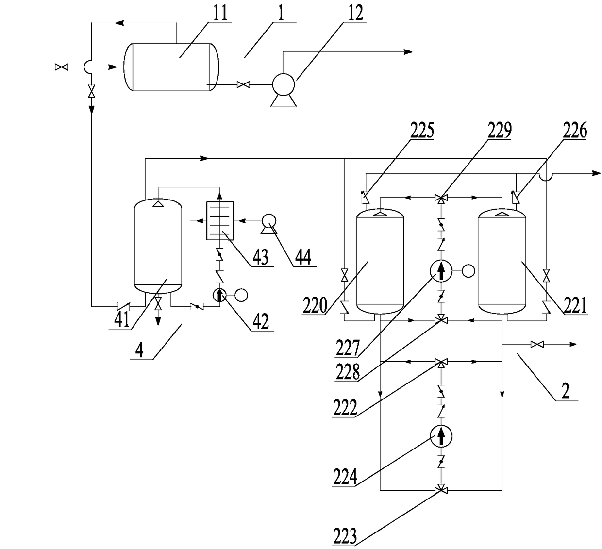
[0068] Such as figure 2 As shown, Embodiment 2 of the present invention provides a hydraulic gas compression purification system, which is similar to the hydraulic gas compression purification system provided in Embodiment 1, including: gas-liquid separation assembly 1, purification compression assembly 2, automatic control Components and cooling separation system4.

[0069] Wherein, the structure, connection mode and operation mode of the gas-liquid separation assembly 1 , the automatic control assembly and the cooling separation system 4 are similar to those in Embodiment 1, and will not be repeated here.

[0070] The difference is that the purification compression assembly 2 includes a first purification compression tank 220, a second purification compression tank 221, a first electric three-way valve 222, a second electric three-way valve 223, a first compression pump 224, a first row Air control valve 225 and second exhaust control valve 226.

[0071] Specifically, the...


PUM


Abstract

The invention discloses a hydraulic gas compression purification system and a compression purification method thereof. The hydraulic gas compression purification system comprises a gas-liquid separation component, a compression purification component and an automatic control component, wherein the gas-liquid separation component is used for performing gas-liquid separation treatment on the inflowliquid containing gas; the compression purification component is used for performing compression purification treatment on the gas; a gas inlet end of the compression purification component is connected with a gas outlet of the gas-liquid separation component through a pipeline; the automatic control component is respectively electrical connected with and is used for controlling the gas-liquid separation component and the compression purification component; the compression purification component is used for performing compression purification treatment on the gas in the manner of draining liquid, sucking gas and compressing inflow liquid by taking purified liquid as compressed liquid. The hydraulic gas compression purification system disclosed by the invention is capable of meeting the requirements for compression purification under various complex working conditions, such as solid impurities contained in the gas-containing liquid, big change on gas content and harmful substances contained in gas in practical application, and has the characteristics of smart design, unique method, high degree of automation and broad practical application prospect.

Description

technical field [0001] The invention belongs to the technical field of separation, purification and compression treatment of gas-containing liquids, and in particular relates to a hydraulic gas compression purification system and a compression purification method thereof. Background technique [0002] In the process of compressing industrial gases, it is often encountered that the gas to be compressed contains solid impurities, the flow rate of the gas to be compressed changes greatly, and the gas to be compressed contains harmful substances, which requires purification and compression. Among them, the gas to be compressed contains solids Impurities will affect the life of the compressor; when the gas to be compressed contains harmful substances, it is necessary to set up a separate device to remove the harmful substances; when the compression volume of the gas to be compressed changes greatly per unit time, it will cause difficulty in selecting the compressor. For example, ...

Claims


Application Information

Patent Timeline
Patent Type & Authority Applications(China)
IPC IPC(8): B01D53/00B01D53/18
CPCB01D53/002B01D53/18
Inventor 王力兴江兴家王进曹慧琴王猛
Owner 克拉玛依九工环保技术有限公司
Learn More