
Metal plate punching device

A technology of stamping equipment and sheet metal, which is applied in the field of sheet metal processing equipment, can solve the problems of poor sheet metal production environment, easily scratched sheet metal parts, and waste materials that cannot be cleaned in time, so as to improve cleaning strength, improve work enthusiasm, Guaranteed neat results

Active Publication Date: 2019-01-18
宁波吉文金属科技有限公司
View PDF7 Cites 4 Cited by
  • Summary
  • Abstract
  • Description
  • Claims
  • Application Information

AI Technical Summary

Problems solved by technology

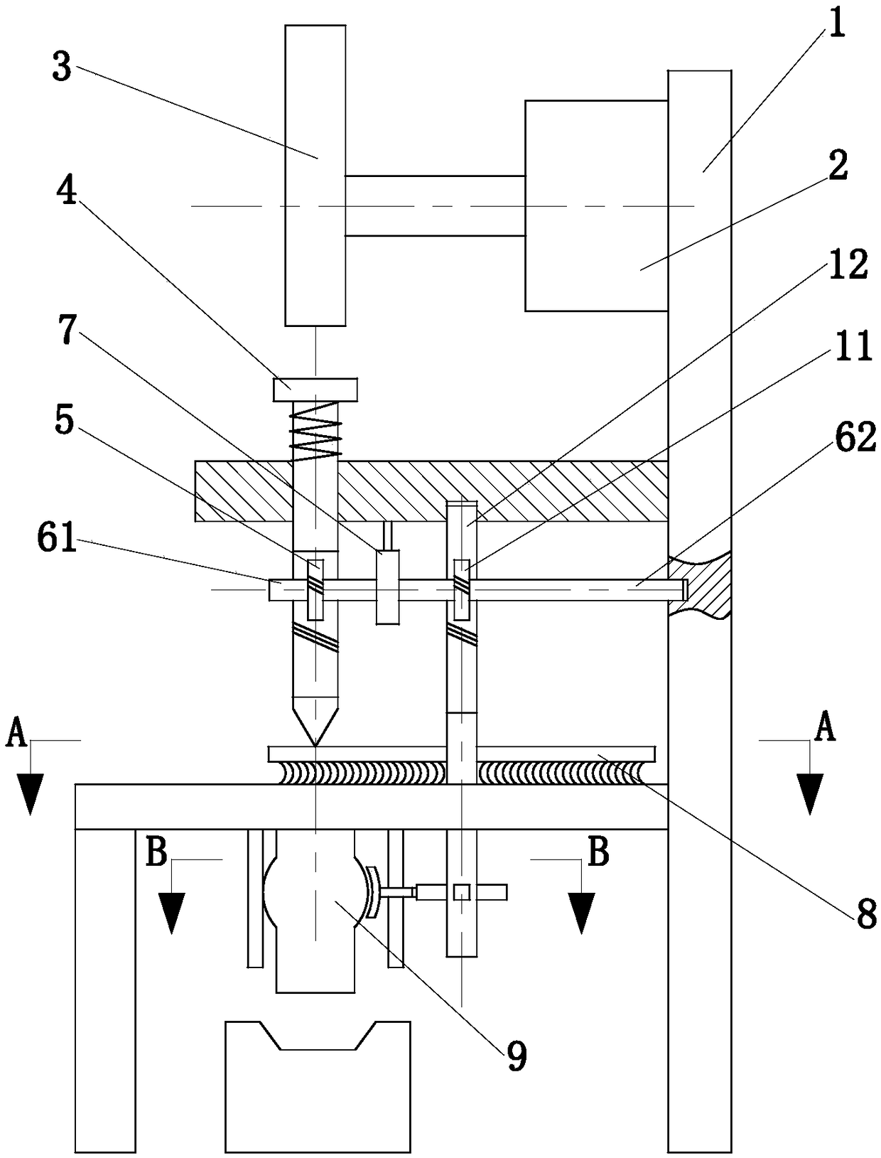
[0005] In order to make up for the deficiencies of the existing technology, the invention proposes a sheet metal stamping equipment. The purpose of the invention is to solve the problem that the waste on the working table cannot be cleaned up in time and easily scratches the sheet metal parts during the sheet metal stamping production process. The problem of poor environment

Method used


Image

  • Metal plate punching device
  • Metal plate punching device
  • Metal plate punching device

Examples


Embodiment Construction

[0022] In order to make it easy to understand the technical means, creative features, goals and effects achieved by the present invention, the present invention will be further explained below in conjunction with specific embodiments.

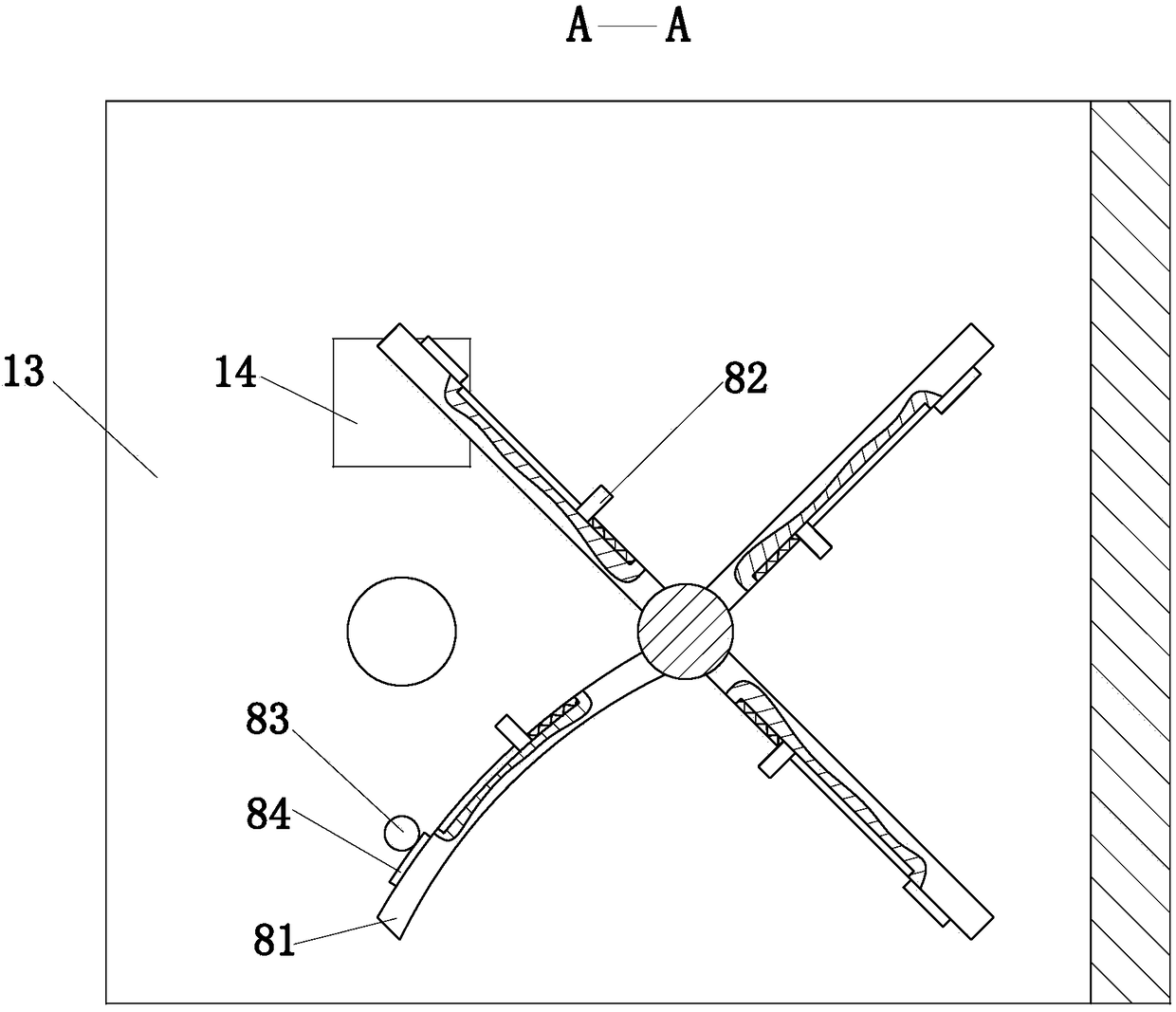
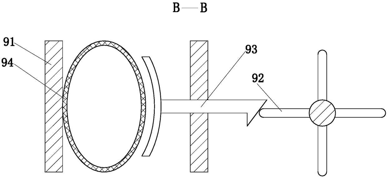
[0023] Such as Figure 1 to Figure 3 As shown, a sheet metal stamping equipment according to the present invention includes a frame 1, a motor 2, an eccentric wheel 3, a punch 4, a gear 5, a left transmission shaft 61, a right transmission shaft 62, a clutch 7, a worm gear 11, Worm 12, cleaning device 8 and storage device 9; the upper part of the frame 1 is provided with a cross beam, the bottom of the frame 1 is provided with a base, the upper part of the base is provided with a working table 13, and the middle of the working table 13 is provided with a chip removal port 14; The motor 2 is installed horizontally on the upper part of the frame 1, and an eccentric wheel 3 is installed on the rotating shaft of the motor 2; the punch 4 is installed o...


PUM


Abstract

The invention belongs to the technical field of metal plate machining devices, and particularly discloses a metal plate punching device. The device comprises a rack, a motor, an eccentric wheel, a puncher pin, a gear, a left transmission shaft, a right transmission shaft, a clutch, a worm wheel ,a worm, a sweeping device and a storing device; the sweeping device is fixed to the middle of the worm,and the sweeping device rotates along with the worm to sweep the working tabletop; the storing device is installed below a base, a solid waste box is placed under the storing device, the storing device works synchronous with the sweeping device through rotation of the worm, and generated waste swept by the sweeping device is collected and discharged into the solid waste box; due to sweeping workof the sweeping device, waste gathered at the working tabletop is removed in time, and it is ensured that the working environment is clean; waste is automatically cleaned day and collected, on-site cleaning work after production ending of production workers is avoided, and working pressure of production workers is relieved; under the effect of the storing device, cleaned waste can be effectively collected, and the purpose of environment-friendly production is achieved.

Description

Technical field [0001] The invention belongs to the technical field of sheet metal processing equipment, specifically a sheet metal stamping equipment. Background technique [0002] Sheet metal has the characteristics of light weight, high strength, electrical conductivity (can be used for electromagnetic shielding), low cost, and good mass production performance. It has been widely used in electronic appliances, communications, automotive industry, medical equipment and other fields, such as in In computer cases, mobile phones, and MP3, sheet metal is an indispensable part. As sheet metal is used more and more widely, the design of sheet metal parts has become a very important part of the product development process. [0003] Some technical solutions for sheet metal stamping have also appeared in the prior art. For example, a Chinese patent with application number 201820236721.6 discloses a sheet metal stamping and cutting equipment, including a main box and an iron sheet. There ...

Claims


Application Information

Patent Timeline
IPC IPC(8): B21D22/02B30B15/00B30B1/26F16F15/023F16F15/08
CPCB21D22/02B30B1/266B30B15/0082F16F15/023F16F15/085
Inventor 周焱春陈壮壮凡得雨
Owner 宁波吉文金属科技有限公司
Learn More