
Trimming mechanism based on automobile injection molding part

A technology for injection molded parts and trimming, which is applied to machine tools, household components, applications, etc., which are suitable for grinding the edge of workpieces. It can solve the problems of reducing processing efficiency and increasing labor, and achieves reducing processing efficiency, increasing labor, and convenience The effect of using

Inactive Publication Date: 2019-01-18
XUZHOU YUNTAI AUTOMOBILE ELECTRICAL APPLIANCE
View PDF5 Cites 7 Cited by
  • Summary
  • Abstract
  • Description
  • Claims
  • Application Information

AI Technical Summary

Problems solved by technology

[0003] The purpose of the present invention is to provide a trimming mechanism based on automotive injection molded parts, which has the advantages of integrating cutting, punching and grinding, and solves the problem of trimming, punching and grinding of automotive injection molded parts in the prior art. The work is carried out separately, which not only increases the workload of people, but also reduces the problem of processing efficiency

Method used

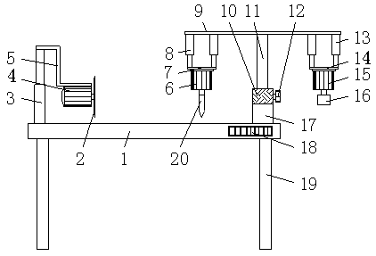

Image

  • Trimming mechanism based on automobile injection molding part
  • Trimming mechanism based on automobile injection molding part
  • Trimming mechanism based on automobile injection molding part

Examples


Embodiment Construction

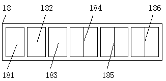
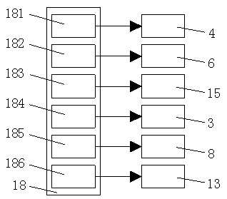
[0016] refer to Figure 1-3 , the present invention comprises a support seat 1, the support legs 19 are fixedly connected around the bottom of the support seat 1, and the bottom of the support legs 19 is fixedly connected with a rubber pad, and the right end of the front surface of the support seat 1 is fixedly connected with a controller 18, and the control The front surface of the device 18 is fixedly connected with the first motor switch 181, the second motor switch 182, the third motor switch 183, the first telescopic control button 184, the second telescopic control button 185 and the third telescopic control button from left to right. 186, the left end of the top of the support seat 1 is fixedly connected with the first electric telescopic rod 3, and the top of the first electric telescopic rod 3 is fixedly connected with the first support plate 5, and the bottom of the first support plate 5 is fixedly installed with the first motor 4 , and the output shaft of the first ...


PUM


Abstract

The invention discloses a trimming mechanism based on an automobile injection molding part. The trimming mechanism based on the automobile injection molding part comprises a supporting base, supporting legs, a bearing pedestal, a supporting rod, a first electric telescopic rod, a second electric telescopic rod and a third electric telescopic rod. The trimming mechanism based on the automobile injection molding part is characterized in that the left end of the top of the supporting base is fixedly connected with the first electric telescopic rod; the top end of the first electric telescopic rodis fixedly connected with a first supporting plate; a first motor is fixedly arranged at the bottom of the first supporting plate; an output shaft of the first motor is fixedly connected with a cutting knife; the right end of the top of the supporting base is fixedly connected with the bearing pedestal; and the top end of the bearing pedestal is fixedly connected with a sleeve. The trimming mechanism based on the automobile injection molding part has the following advantage: the problems in the prior art that the trimming work such as cutting, punching and polishing of the automobile injection molding part is conducted separately, the labor amount of people is increased and the processing efficiency is reduced are solved. The requirement on horizontal rotation of the supporting rod and afourth supporting plate by people can be met, so that people can use a drill rod and a grinding head conveniently.

Description

technical field [0001] The invention relates to the technical field of automobile injection molded parts, in particular to a trimming mechanism based on automobile injection molded parts. Background technique [0002] With the rapid development of society, people's economic level is also constantly improving. More and more families have bought cars. There are many types of cars and their prices vary greatly. People use cars for a wide range of purposes. Today, plastics are already an important part of automobiles. In developed countries, the amount of plastics used in automobiles has even become an important symbol to measure the level of automobile design and manufacturing. After injection molding, automobile plastic products need to be trimmed However, in the prior art, the cutting, punching and grinding of automobile injection molded parts are performed separately, which not only increases people's labor, but also reduces the processing efficiency. Therefore, we propose a...

Claims


Application Information

Patent Timeline
Patent Type & Authority Applications(China)
IPC IPC(8): B29C37/02B26F1/16B24B9/20B29L31/30
CPCB24B9/20B26F1/16B29C37/02B29L2031/30
Inventor 王满知
Owner XUZHOU YUNTAI AUTOMOBILE ELECTRICAL APPLIANCE
Learn More