Numerical-control automatic cam lathe

An automatic lathe and cam technology, which is applied in the field of lathes, can solve the problems of low machining accuracy, low labor efficiency, and large power consumption, etc., and achieve the effects of improving product processing progress, improving labor efficiency, and ensuring dimensional accuracy

Inactive Publication Date: 2013-09-11
JIANGSU TANGYIN PHOTOELECTRIC
View PDF5 Cites 4 Cited by
  • Summary
  • Abstract
  • Description
  • Claims
  • Application Information

AI Technical Summary

Problems solved by technology

[0003] (1) In the original general-purpose CNC lathe, the outer circle, inner hole, end face, and outer thread of the processing parts need to be completed step by step by division of labor. The workpiece clamping cannot be fully automated. Each part needs to be clamped manually, and the processing speed Slow, low labor efficiency, high manufacturing cost;
[0004] (2) For the original cam bicycle, although each part can be loaded into the fixture when processing the parts, the machining of the outer circle, inner hole, end face, and outer thread of the parts requires multiple automatic lathes to be distributed and completed multiple times. In the material, the processing accuracy and concentricity are prone to accumulated errors, resulting in low processing accuracy of the parts, and the use of multiple cam lathes consumes a lot of power and increases production costs;
[0005] (3) It is not easy to adjust the size of the part car on the machine tool, and the operator needs to have a certain level of skill

Method used


Image

  • Numerical-control automatic cam lathe
  • Numerical-control automatic cam lathe
  • Numerical-control automatic cam lathe

Examples


Embodiment Construction

[0015] Below in conjunction with accompanying drawing and specific embodiment, further illustrate the present invention, should be understood that these embodiments are only for illustrating the present invention and are not intended to limit the scope of the present invention, after having read the present invention, those skilled in the art will understand various aspects of the present invention Modifications in equivalent forms all fall within the scope defined by the appended claims of this application.

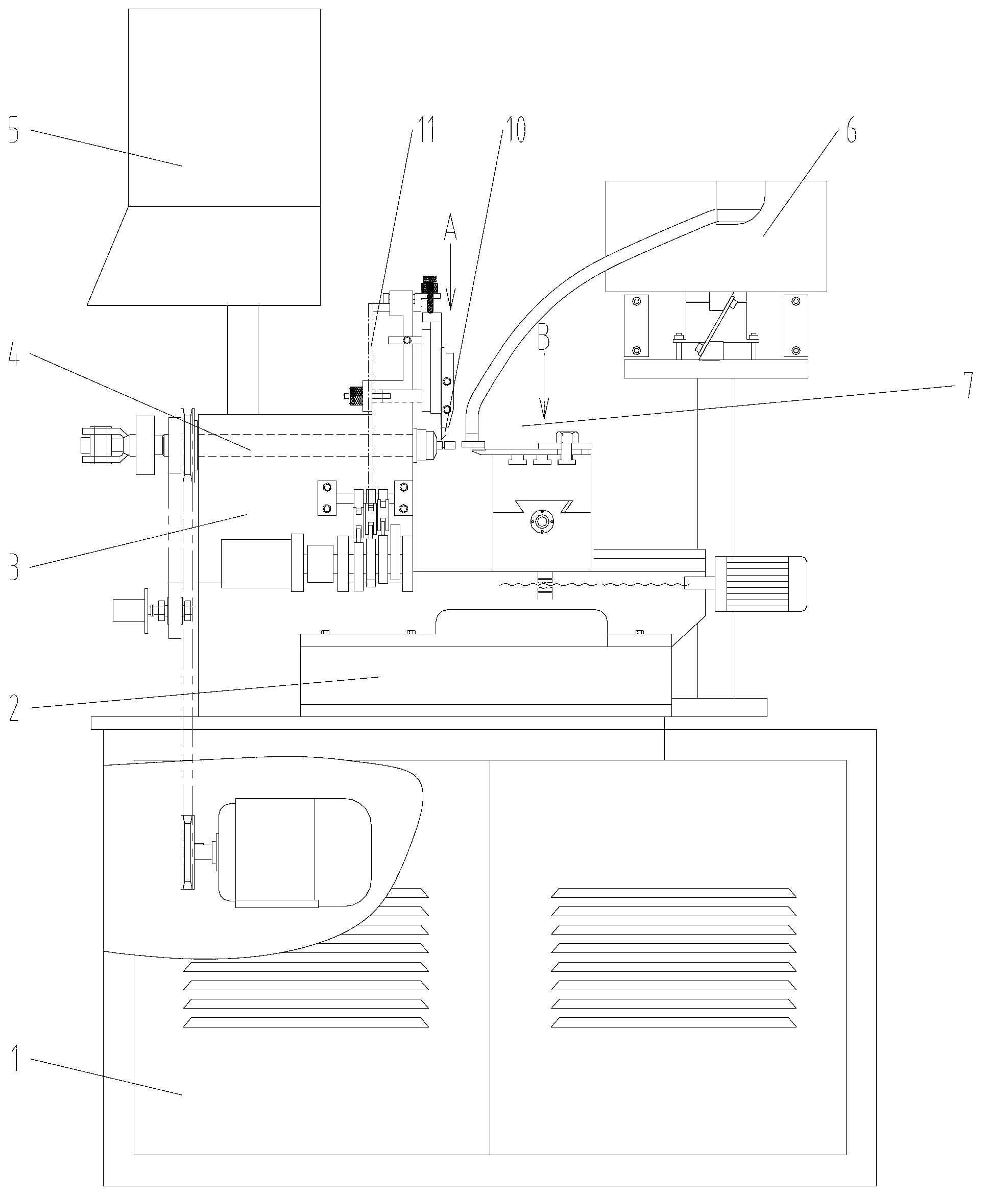
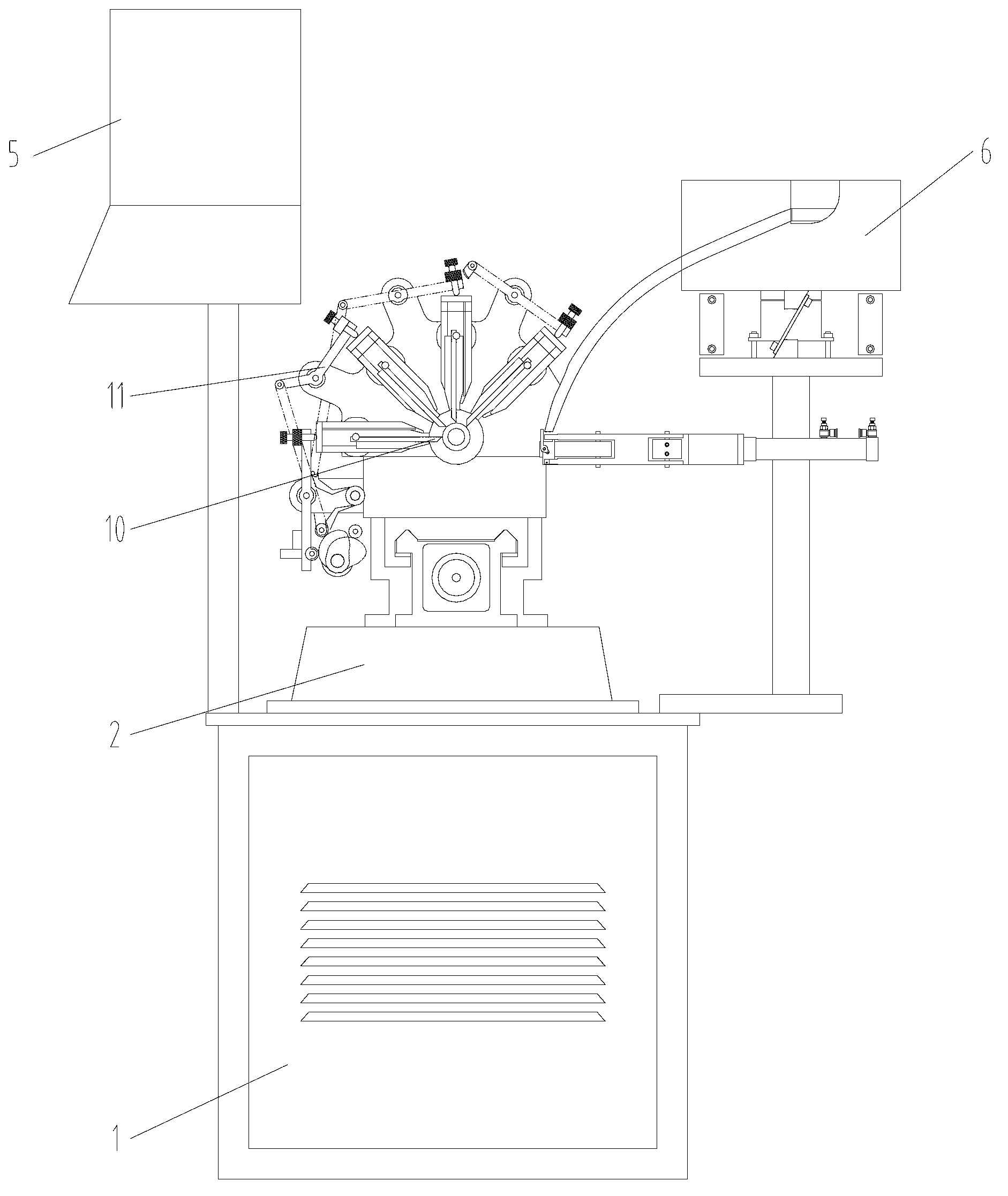
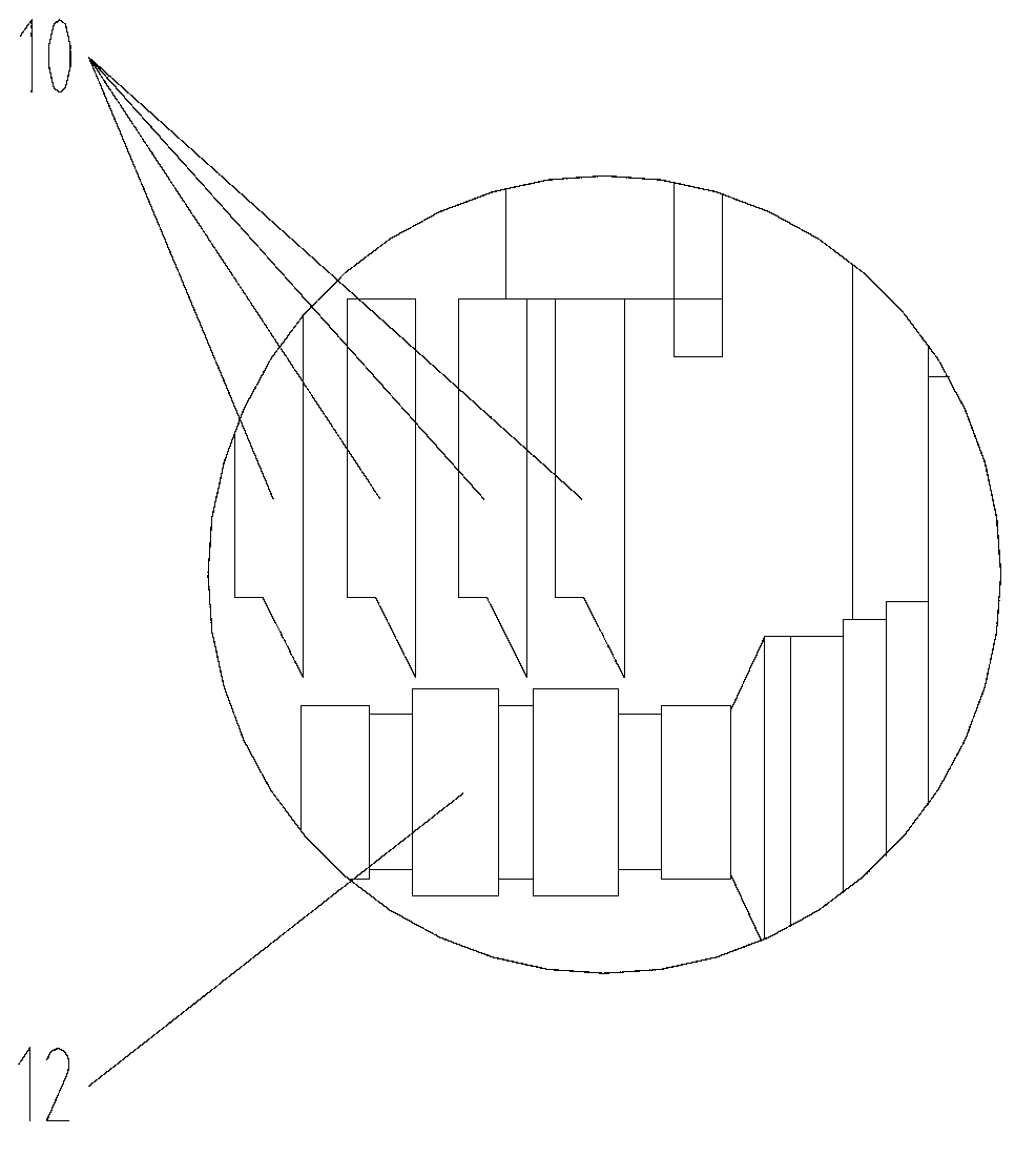
[0016] as attached figure 1 , 2 As shown, a CNC cam automatic lathe includes a frame 1, a machine base 2, a machine head 3, a spindle 4, a CNC manipulator 5, a feeding device 6, and a CNC tool rest 7, and the feeding device 6 adopts a vibrating feeder, The top of the main shaft 4 can hold the workpiece and be driven to rotate by power. The workpiece 12 is fed to the machine head 3 by the feeding device 6 and the top of the main shaft 4 is clamped and fixed. Through the...


PUM


Abstract

The invention discloses a numerical-control automatic cam lathe comprising a frame, an engine base, a nose, a spindle, a numerical-control operator, a feed device and a numerical-control cutter rest. The numerical-control cutter rest is provided with an X-axis cutter, a Y-axis cutter and a Z-axis cutter, and the Z-axis cutter is driven by an eccentric cam connecting rod mechanism. The numerical-control automatic cam lathe has the advantages that the eccentric cam connecting rod mechanism controls cutter feed, is combined with numerical control and the like to perform fine operation and guarantee size accuracy in product processing; workpiece clamping is completed through automatic feeding, labor is reduced and labor efficiency is improved; cut workpieces are automatically fixed, multi-directional cutting can be realized, cutting requirements of different shapes are met, the same workpiece can be processed and formed on the lathe at one step without frequent changing devices, full-automatic cutting process is realized, processing size and shape and position tolerance of the workpiece are guaranteed, and production efficiency and product processing speed are effectively improved.

Description

technical field [0001] The invention relates to a lathe, in particular to a lathe which meets various processing requirements and processes high-precision parts. Background technique [0002] Lathe is a kind of commonly used cutting processing equipment. Several existing lathes have the following problems: [0003] (1) In the original general-purpose CNC lathe, the outer circle, inner hole, end face, and outer thread of the processing parts need to be completed step by step by division of labor. The workpiece clamping cannot be fully automated. Each part needs to be clamped manually, and the processing speed Slow, low labor efficiency, high manufacturing cost; [0004] (2) For the original cam bicycle, although each part can be loaded into the fixture when processing the parts, the machining of the outer circle, inner hole, end face, and outer thread of the parts requires multiple automatic lathes to be distributed and completed multiple times. In the material, the process...

Claims


Application Information

Patent Timeline
Patent Type & Authority Applications(China)
IPC IPC(8): B23B7/14B23Q5/22B23B15/00
Inventor 谢萌张彪张家铁
Owner JIANGSU TANGYIN PHOTOELECTRIC
Why Eureka
Try Eureka