
Battery necking machine

A battery and shrinking technology, applied in the manufacturing of primary batteries, secondary batteries, circuits, etc., can solve the problems of no shrinking equipment for remedial work, unreasonable sealing equipment design, insufficient battery sealing pressure, etc., to increase the burst pressure and Charge and discharge performance, improved usability, reduced shoulder height

Active Publication Date: 2017-08-18
ZHENGJIANG MUSTANG BATTERY CO LTD
View PDF5 Cites 0 Cited by
  • Summary
  • Abstract
  • Description
  • Claims
  • Application Information

AI Technical Summary

Problems solved by technology

[0002] The existing battery manufacturing process mainly includes: positive and negative electrode ingredients, coating, sheet production, winding, shelling, liquid injection, sealing, chemical formation and other technological processes. The battery is sealed many times. If the shoulder height of the battery is too high after sealing, the sealing pressure of the battery will be insufficient and liquid leakage will occur. Therefore, the battery sealing operation is the main factor affecting the charging and discharging performance of the battery.
In the existing sealing process, due to the unreasonable design of the sealing equipment and the lack of corresponding shrinking equipment for follow-up remedial work, the shoulder height of some batteries that have undergone multiple sealing operations may have excessive problems, which brings great harm to users. Inconvenience
For example, the invention patent application with the patent number of 201510464482.0 and the title of "a lithium battery sealing machine" includes a punch press. There is a mold between them. The mold includes an upper mold and a lower mold. The upper mold is fixedly installed at the lower end of the punch connecting rod. The lower mold includes two oppositely arranged monomers. The inner surface of each monomer is recessed outward to form a clamping groove. The clamping groove is semi-cylindrical; the fixed plate is fixedly connected with the cylinder and the positioning plate, the free end of the piston rod of the cylinder is connected with the feeding slider, and the positioning plate is provided with a chute, the opening of the chute faces the feeding slider, and one of the lower The single unit of the die is fixedly connected to the side of the feeding slider, and the single unit of the other lower die is fixedly connected to the inner end of the chute, that is, there may be a problem of the height of the battery shoulder after sealing

Method used


Image

  • Battery necking machine
  • Battery necking machine
  • Battery necking machine

Examples


Embodiment Construction

[0026] The present invention will be further described in detail below in conjunction with the accompanying drawings and embodiments.

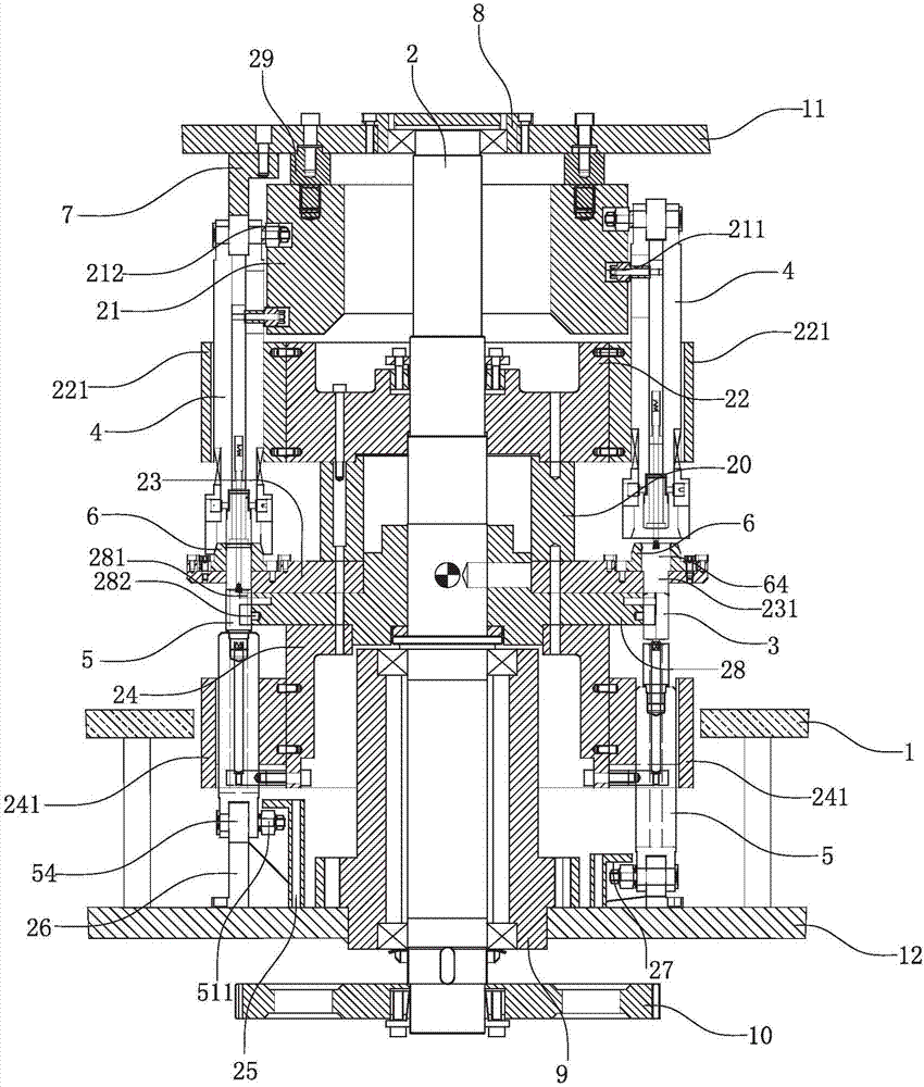
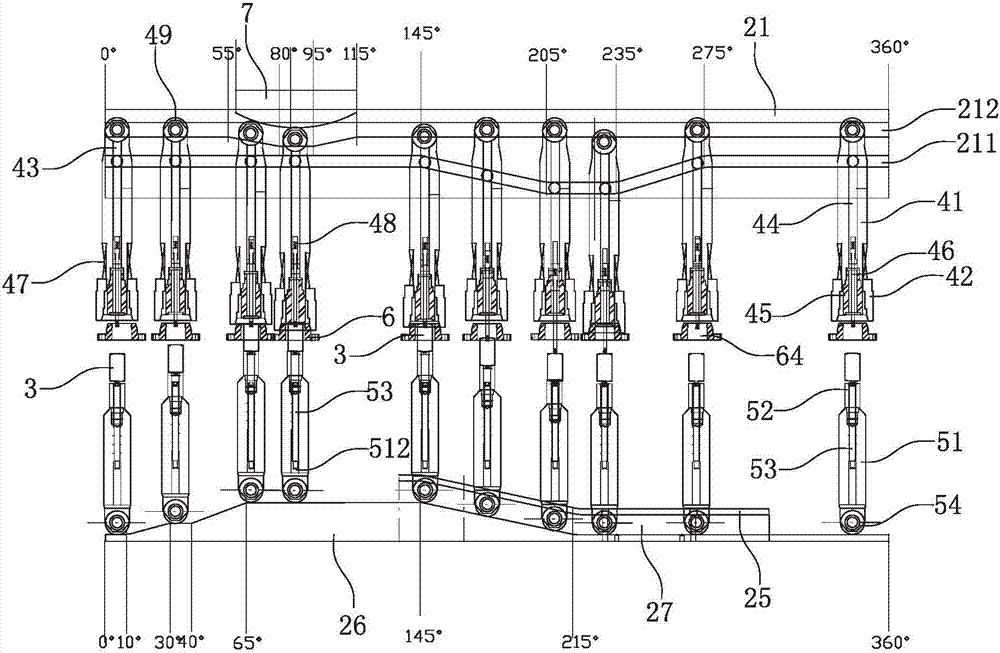
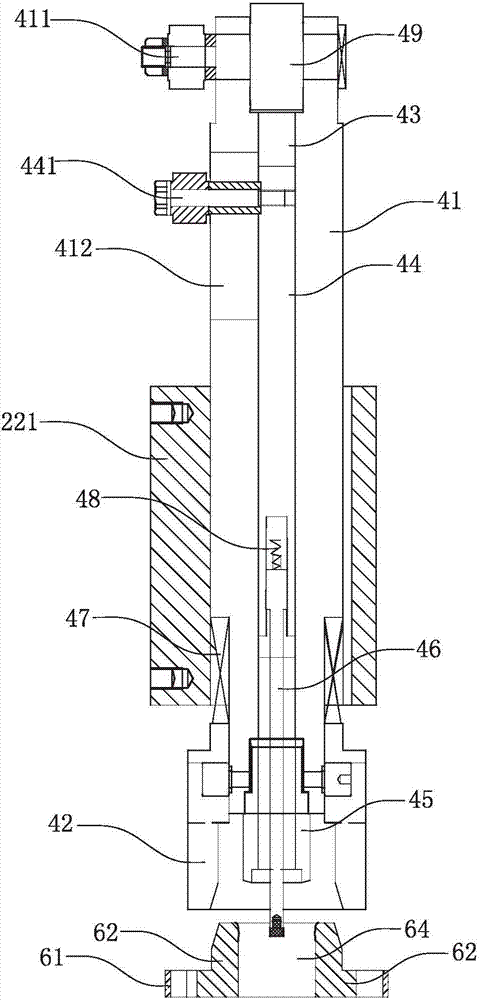
[0027] Such as Figure 1-6 As shown, the embodiment of the present invention provides a battery shrinking machine, including a frame 1, a rotating shaft 2 arranged on the frame 1 is rotated vertically, and a drive assembly (not shown) for driving the rotating shaft 2 to rotate The rotating shaft 2 is provided with a depression bar lifting cam 21, a depression bar rotating wheel 22, a rotating disk 23, a pushing rod rotating wheel 24 and a lower cam 26 for lifting the pushing rod in turn on the rotating shaft 2. The rod lift guide surface 25, the push rod lift cam 21, the push rod lift guide surface 25 and the push rod lift lower cam 26 are respectively fixed with the frame 1, the push rod rotating wheel 22, the turntable 23, the push rod rotating wheel 24 are fixed with the rotating shaft 2 And rotate with the rotating shaft 2 in the same dir...


PUM


Abstract

A battery necking machine comprises a rack, a rotation shaft and a driving assembly, wherein the rotation shaft is arranged on the rack, a press rod lifting cam, a press rod rotation wheel, a rotation disc, a top rod rotation wheel and a top rod lifting lower cam are sleeved on the rotation shaft, a top rod lifting guide surface is arranged between the rotation shaft and the top rod lifting lower cam, the press rod lifting cam, the top rod lifting guide surface and the top rod lifting lower cam are fixed with the rack, the press rod rotation wheel, the rotation disc and the top rod rotation wheel are fixed with the rotation shaft and rotate with the rotation shaft, the press rod assembly is circumferentially arranged on the press rod rotation wheel, rotates in the same direction of the press rod rotation wheel and upwards and downwards moves relative to the press rod rotation wheel, a top rod assembly is circumferentially arranged on the top rod rotation wheel, rotates in the same direction of the press rod rotation wheel and upwards and downwards moves relative to the top rod rotation wheel, station holes are formed in the rotation disc and are arranged between the press rod assembly and the top rod assembly, the press rod lifting cam is connected with the press rod assembly so as to guide the press rod assembly to upwards and downwards move, and the top rod assembly is guided to upwards and downwards move between the top rod lifting guide surface and the top rod lifting low cam. The top rod assembly is used for positioning a lower end of a battery, the press rod assembly is used for stamping a shoulder part of the battery so as to reduce shoulder height, and the burst pressure of the battery is increased.

Description

technical field [0001] The invention relates to the technical field of battery production, in particular to a battery shrinking machine. Background technique [0002] The existing battery manufacturing process mainly includes: positive and negative electrode ingredients, coating, sheet production, winding, shelling, liquid injection, sealing, chemical formation and other technological processes. The battery is sealed many times. If the shoulder height is too high after the battery is sealed, the sealing pressure of the battery will be insufficient and liquid leakage will occur. Therefore, the battery sealing operation is the main factor affecting the battery charge and discharge performance. In the existing sealing process, due to the unreasonable design of the sealing equipment and the lack of corresponding shrinking equipment for follow-up remedial work, the shoulder height of some batteries that have undergone multiple sealing operations may have excessive problems, which...

Claims


Application Information

Patent Timeline
Patent Type & Authority Applications(China)
IPC IPC(8): H01M6/00H01M10/04
CPCH01M6/005H01M10/04Y02P70/50Y02E60/10
Inventor 余谷峰宋西章
Owner ZHENGJIANG MUSTANG BATTERY CO LTD
Learn More