Machining tool, machining system and machining method for handle part

A handle and parts technology, applied in the field of handle parts processing, can solve problems such as handle part opening deformation, achieve the effects of improving efficiency, ingenious and novel structural design, and reducing costs

Pending Publication Date: 2022-04-01
石家庄达辛科技有限公司
View PDF9 Cites 0 Cited by
  • Summary
  • Abstract
  • Description
  • Claims
  • Application Information

AI Technical Summary

Problems solved by technology

[0005] One of the objectives of the present invention is to provide a processing tool for handle parts to solve the problem of deformation of the handle part opening in the above-mentioned existing handle part processing method

Method used


Image

  • Machining tool, machining system and machining method for handle part
  • Machining tool, machining system and machining method for handle part
  • Machining tool, machining system and machining method for handle part

Examples


Embodiment 1

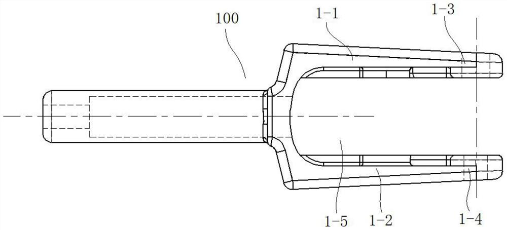
[0052] Such as Figure 4 As shown, this embodiment provides a processing tooling 100 for handle parts, which mainly includes a base plate 2, a positioning plate 4 and a part fixture 6. The upper surface of one side of the base plate 2 is provided with a first positioning surface 3; the positioning plate 4 is arranged on the base plate 2; the positioning plate 4 is located above the first positioning surface 3, and is spaced apart from the first positioning surface 3, and the upper surface of the positioning plate 4 is provided with a second positioning surface 5; the positioning plate 4 is used for fitting the handle part blank 1 Handle opening 1-5, wherein, handle opening 1-5 needs to process the side plate of threaded hole 1-4 (ie figure 1 The second opening side plate 1-2 shown) is located between the positioning plate 4 and the first positioning surface 3, and the side plate (ie, figure 1 The bottom surface of the shown second opening side plate 1-2) is veneered support; ...

Embodiment 2

[0065] This embodiment proposes a processing system for handle parts, including a machining center for machining a handle part blank 1 and a processing tool 100 for handle parts as described in Embodiment 1.

[0066] In this embodiment, as a preferred manner, the above-mentioned machining center adopts a three-axis machining center. The three-axis machining center can be used to process through holes 1-3 and threaded holes 1-4. It is an existing machining center. The specific structure and working principle will not be repeated here. It has high work efficiency and low cost, and can overcome the current situation. There are four-axis machining centers with four-axis repeated rotation, long auxiliary man-hours, low processing efficiency, and high cost.

Embodiment 3

[0068] This embodiment proposes a processing method for a handle part, which is implemented by using the processing tool for the handle part as described in Embodiment 1, and specifically includes the following steps:

[0069] Install the handle part blank 1 to be processed on the processing tool 100 of the handle part, and make the tail end of the handle part blank 1 cooperate with the part fixture 6, and the handle opening 1-5 is set on the positioning plate 4, and the handle opening 1-5 The side plate of the threaded hole 1-4 that needs to be processed is located between the positioning plate 4 and the first positioning surface 3, and is supported by the first positioning surface 3. The side of the handle opening 1-5 that needs to process the through hole 1-3 The plate is located above the positioning plate 4 and is veneered supported by the second positioning surface 5;

[0070] Process the through hole 1-3 on the side plate that needs to process the through hole 1-3 of th...


PUM


Abstract

The handle part machining tool comprises a bottom plate, a positioning plate and a part clamp, a first positioning face is arranged on the upper surface of one side of the bottom plate, the positioning plate is arranged on the bottom plate, the positioning plate and the first positioning face are arranged in a spaced mode, and a second positioning face is arranged on the upper surface of the positioning plate; the part clamp is arranged on the side, away from the first positioning face, of the bottom plate and used for being connected with the tail end of the handle part blank. The machining tool is ingenious and novel in structural design, the first positioning face is arranged to carry out veneering supporting on the side plate, needing threaded hole machining, of the handle opening, the second positioning face is arranged to carry out veneering supporting on the side plate, needing through hole machining, of the handle opening, and the problem that the side plate deforms and collapses due to the fact that the side plate of the handle opening is directly punched can be effectively solved. The invention further provides a processing system and a processing method of the handle part, the processing size of the handle part blank can be ensured on the premise of ensuring reliable tool positioning, meanwhile, the processing efficiency is improved, and the production cost is reduced.

Description

technical field [0001] The invention relates to the technical field of handle parts processing, in particular to a processing tool, a processing system and a processing method for handle parts. Background technique [0002] Such as figure 1 Shown is the blank 1 of the handle part to be processed, which is generally made of metal, such as stainless steel 304, and the blank of the handle part is mostly made of silica sol precision casting and mass-produced. The handle part blank 1 includes a first opening side plate 1-1 and a second opening side plate 1-2, a handle opening 1-5 is formed between the first opening side plate 1-1 and the second opening side plate 1-2, and the second opening side plate 1-2 forms a handle opening 1-5. One of an opening side plate 1-1 and the second opening side plate 1-2 needs to offer a through hole 1-3, and the other needs to offer a threaded hole 1-4, and the through hole 1-3 and the threaded hole 1-4 It needs to be coaxial, and the diameter o...

Claims


Application Information

Patent Timeline
Patent Type & Authority Applications(China)
IPC IPC(8): B23Q3/00
Inventor 张百勇张艳华司鹏飞米天旺
Owner 石家庄达辛科技有限公司
Why Eureka
Try Eureka