an injection molding machine

A technology of injection molding machine and rack, applied in the field of plastic production equipment, can solve the problems of time and labor waste, reduced production efficiency of injection molding machine, melting, etc., to achieve the effect of saving cost, reducing mold change time, and good quality of finished products

Active Publication Date: 2020-08-18
邵东市顺发工业有限公司
View PDF3 Cites 2 Cited by
  • Summary
  • Abstract
  • Description
  • Claims
  • Application Information

AI Technical Summary

Problems solved by technology

For existing injection molding machines, the usual injection molding mode is single-station, that is, a fixed mold is equipped with a movable mold to work, and the plastic particles melt in the heating cavity, and there will be some impurities in the melted liquid, which usually needs to be manually disassembled. The switch door of the injection molding machine is opened, and the products after injection molding are manually taken out and placed in the finished product collection tank to realize the discharge of the products in the injection molding machine. The huge waste on the machine will also greatly reduce the production efficiency of the injection molding machine

Method used


Image

  • an injection molding machine
  • an injection molding machine
  • an injection molding machine

Examples


Embodiment Construction

[0027] The following will clearly and completely describe the technical solutions in the embodiments of the present invention with reference to the accompanying drawings in the embodiments of the present invention. Obviously, the described embodiments are only some, not all, embodiments of the present invention. Based on the embodiments of the present invention, all other embodiments obtained by persons of ordinary skill in the art without making creative efforts belong to the protection scope of the present invention.

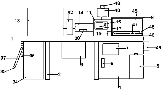
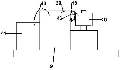
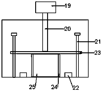
[0028] see Figure 1-5 , the present invention provides a technical solution: an injection molding machine, including a frame 1, a supporting leg 2 is provided under the frame 1, a motor 3 is provided on the left side of the bottom of the frame 1, and a motor 3 is provided under the frame 1. The right side is provided with a cabinet 4, the inner wall of the cabinet 4 is provided with a dehumidifier 5 and the outer wall is provided with a cabinet door 6, the su...


PUM


Abstract

The invention discloses an injection molding machine. The injection molding machine comprises a rack, wherein a supporting leg is arranged below the rack; a motor is arranged at the left side below the rack; a cabinet is arranged at the right side below the rack; a dehumidification device is arranged on an inner wall of the cabinet and a cabinet door is arranged on an outer wall of the cabinet; acontrol panel is arranged on the surface of the cabinet door; the control panel is connected with a motor; an extruding machine, a feeding barrel, a heating cavity, a filtering cavity and a power device are arranged above the rack in sequence from front to back; the extruding machine and a driving device are connected and the driving device is located at one side of the rack; the extruding machineis connected to an inner wall of the heating cavity; the heating cavity is connected with the filtering cavity through a material conveying pipeline; a temperature detector is mounted on the inner wall of the heating cavity, and a temperature controller and a temperature display instrument are arranged on the surface of the heating cavity; a treatment box is arranged at the top of the feeding barrel and the treatment box is connected with a dehumidifier. The injection molding machine is simple in structure and convenient to use; the production cost is greatly saved, and the injection moldingtemperature can be monitored in real time; impurities in melted plastic grains can be filtered and the working efficiency is improved.

Description

technical field [0001] The invention relates to the technical field of plastic production equipment, in particular to an injection molding machine. Background technique [0002] With the development of industrial technology, high-end industrial production has gradually entered people's lives. The production and design of various designed products need to go through several steps such as drawing design, mold shaping and manufacturing. Injection molds are the most widely used in current industrial production. One of the most widely used molds is a processing method used in the mass production of certain complex-shaped parts. Injection molding machines, also known as injection molding machines or injection machines, can make thermoplastics or thermosetting plastics into various plastic molding molds. The main molding equipment for shaped plastic products. For existing injection molding machines, the usual injection molding mode is single-station, that is, a fixed mold is equip...

Claims


Application Information

Patent Timeline
Patent Type & Authority Patents(China)
IPC IPC(8): B29C45/03B29C45/18B29C45/72B29C45/78B29C45/17
CPCB29C45/03B29C45/17B29C45/18B29C45/72B29C45/78
Inventor 陆军刘祎顾波
Owner 邵东市顺发工业有限公司
Why Eureka
Try Eureka