Concealed autonomous flying miniature unmanned aerial vehicle

An unmanned aerial vehicle, a concealed technology, applied in the field of unmanned aerial vehicles, can solve the problems of difficult flight control, cumbersome manufacturing and processing, and difficulty in rapid production of micro-UAVs, so as to improve the practical value and tactical value, and increase the flight distance. and flight time, the effect of avoiding radar detection

Active Publication Date: 2019-01-18
ACAD OF OPTO ELECTRONICS CHINESE ACAD OF SCI
View PDF6 Cites 3 Cited by
  • Summary
  • Abstract
  • Description
  • Claims
  • Application Information

AI Technical Summary

Problems solved by technology

At the same time, it often uses methods such as mold opening to manufacture the fuselage and wings. The manufacturing process is cumbersome and expensive, and electronic components need to be manually installed inside the fuselage, which has resulted in mass and rapid production of micro drones. difficulty
Due to the strict requirements on the weight of the load of the micro-UAV, if the load is heavy, the take-off weight of the aircraft will be too large and it will not be able to fly
[0004] Although micro-UAVs have immeasurable military and civilian potential, from the current technical point of view, it is difficult to put them into application at the current stage, mainly reflected in: (1) limited battery energy leads to flight time Short and short voyage; (2) The power system consumes a lot of energy, which leads to limited energy allocated to the task load, and the working time of the task load is relatively short; (3) The requirement for lightweight is extremely strict, and the task load that can meet the weight requirement is limited; (4) Low-speed flight leads to great difficulty in flight control in complex wind field environments; (5) Core problems such as cumbersome production and processing, low processing precision, and long production cycle need to be further overcome by technicians

Method used


Image

  • Concealed autonomous flying miniature unmanned aerial vehicle
  • Concealed autonomous flying miniature unmanned aerial vehicle
  • Concealed autonomous flying miniature unmanned aerial vehicle

Examples


Embodiment Construction

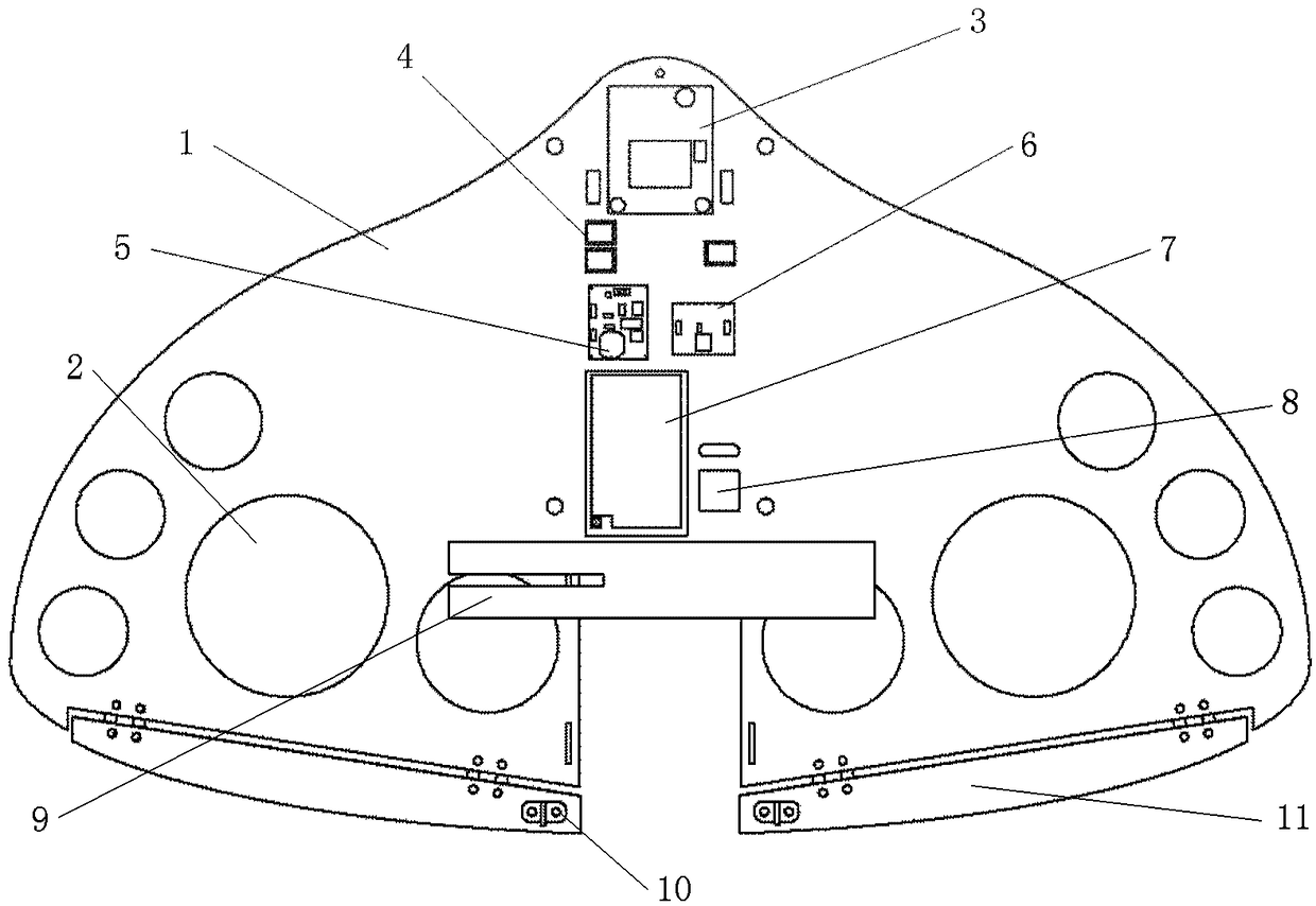
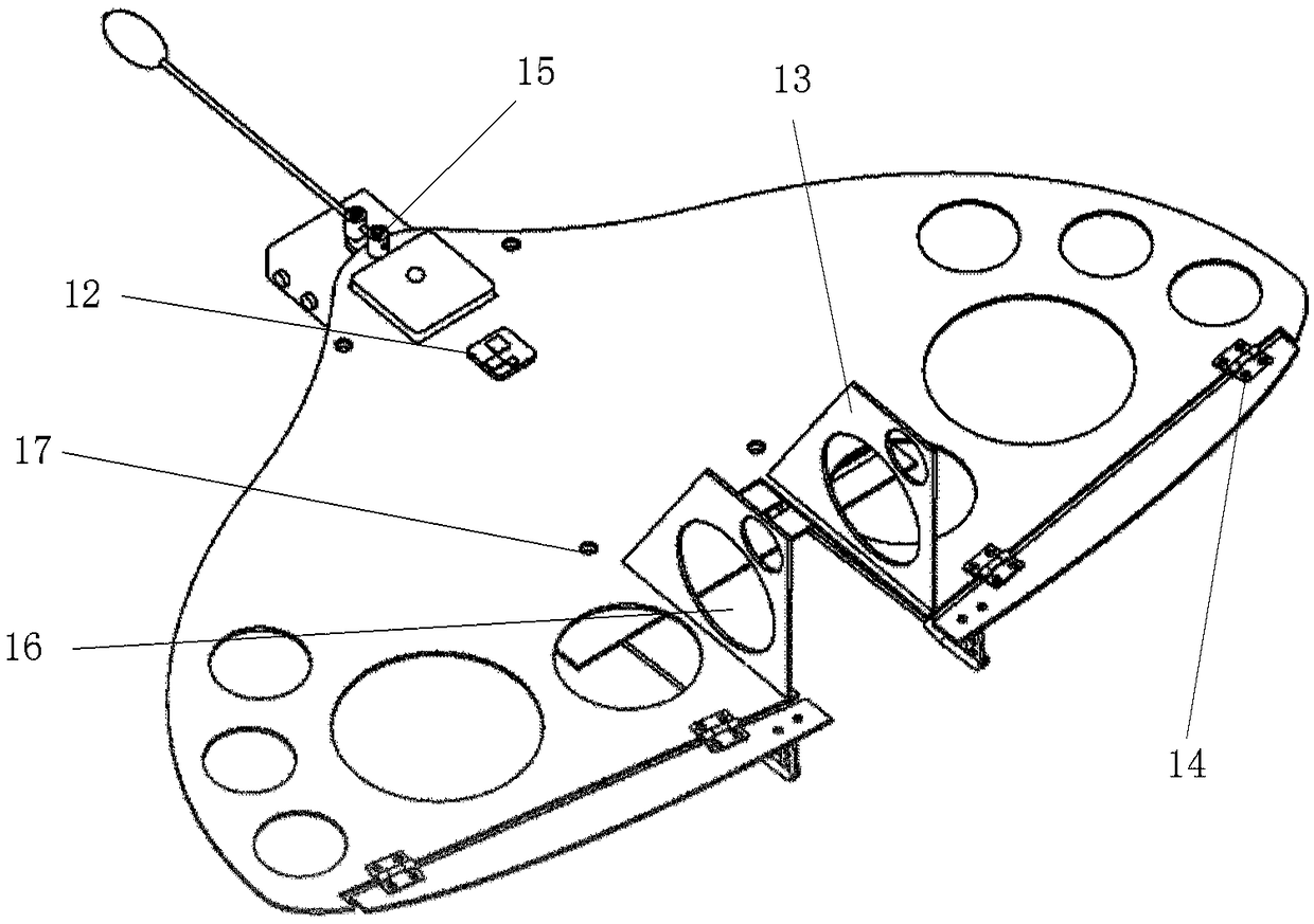
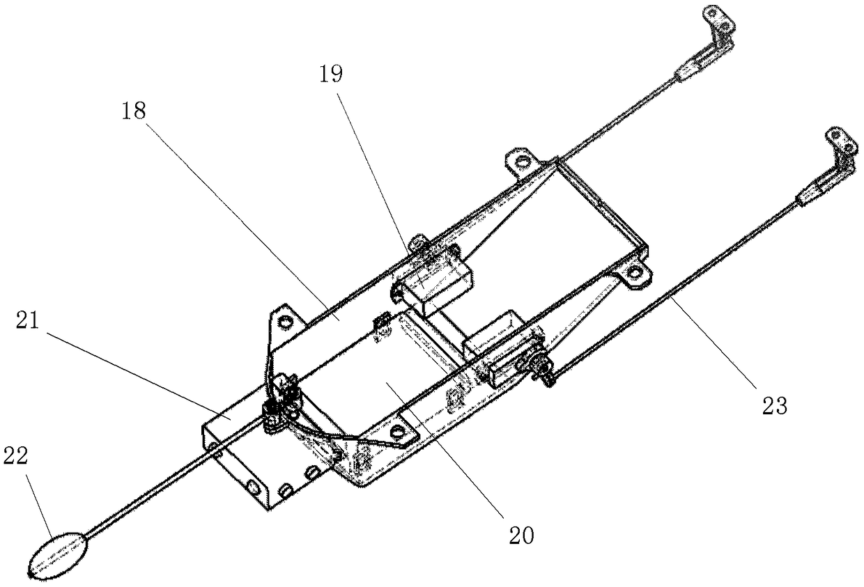
[0048] The present disclosure provides a concealed self-flying miniature unmanned aerial vehicle, including: wings, electronic components, fuselage, rudder surfaces, tail fins, steering gear, connecting rods and batteries; the wings are made of PCB boards; the electronic components are welded On the lower surface of the wing, and the electronic components are evenly distributed on both sides of the central axis of the wing; the fuselage cover is arranged on the electronic component and connected with the lower surface of the wing; The tail is connected; the steering gear is embedded in the mounting holes reserved on both sides of the fuselage; the first end of the connecting rod is connected to the steering gear, and the second end of the connecting rod is connected to the steering surface; the battery is installed inside the fuselage. This disclosure does not set the power device and adopts the design of autonomous gliding flight, so that the drone can work for a longer time a...


PUM


Abstract

A concealed autonomous flying miniature unmanned aerial vehicle (UAV) is provided, which comprises a wing, an electronic assembly, a fuselage, a rudder surface, a tail, a steering gear, a connecting rod and a battery. The wing is made of PCB. An electronic assembly is welded on the lower surface of the wing, and the electronic assembly is uniformly distributed on both sides of the wing central axis; The fuselage cover is arranged on the electronic assembly and is connected with the lower surface of the wing; The rudder surface is connected to the tail of the wing; The tail wing is connected with the tail of the upper surface of the wing; The steering gear is embedded at the mounting holes reserved on both sides of the fuselage; The first end of the connecting rod is connected with the steering gear, and the second end of the connecting rod is connected with the rudder surface; The battery is located inside the fuselage. As that pow device is not provided with the design of high-altitude delivery and autonomous glide flight, the unmanned aerial vehicle can work for longer time and the fault tolerance rate of task execution is increased; At the same time, due to the advantages of material and size, it can also keep good concealment, which greatly increases the practical value and tactical value.

Description

technical field [0001] The present disclosure relates to the field of unmanned aerial vehicles, in particular to a concealed autonomous flying miniature unmanned aerial vehicle. Background technique [0002] In today's world, drones play an irreplaceable role in military and civilian fields. Among them, micro UAVs have immeasurable potential in military value due to their good concealment and practicality. [0003] Due to its small size (generally the wingspan is less than 30 cm) and light weight (generally less than 200 grams), the micro UAV has strict requirements on the selection of energy power system and electronic components. The energy power system of micro-UAVs often uses battery-driven propellers for powered flight. The current micro-UAVs generally fly with power for less than 30 minutes, with speeds lower than 20m / s and unable to have long-distance flight capabilities. When it is launched, the operator must be required to bring the assembly to the area near the t...

Claims


Application Information

Patent Timeline
Patent Type & Authority Applications(China)
IPC IPC(8): B64C31/02B64C39/02
CPCB64C31/02B64C39/02B64U70/20B64U10/25
Inventor 屈正宇郝勇杨燕初闫峰李崔春
Owner ACAD OF OPTO ELECTRONICS CHINESE ACAD OF SCI
Why Eureka
Try Eureka