Eureka AIR delivers breakthrough ideas for toughest innovation challenges, trusted by R&D personnel around the world.

PCB circuit board delivery device

A technology for PCB circuit boards and transportation devices, which is applied in the direction of transportation and packaging, containers and containers to prevent mechanical damage, etc. It can solve the problems of PCB circuit board vibration, PCB circuit board function damage, easy to fall into dust, etc., to speed up speed, slow damage, reduce damage effect

Inactive Publication Date: 2019-01-18
李建
View PDF0 Cites 1 Cited by
  • Summary
  • Abstract
  • Description
  • Claims
  • Application Information

AI Technical Summary

Problems solved by technology

[0004] In the above patent document 1, by laying a rubber plate on the surface of the deck, the phenomenon of scratching the PCB circuit board is eliminated, and the spring is embedded in the bottom of the lower deck to increase the shock absorption effect; Silicone sealing rings are set on the inner wall of the board and the box body, and the flow rate of air in the sealed space is controlled by controlling the size of the buffer hole, thereby realizing the buffering effect on the PCB circuit board; but in the process of improving the buffering effect on the PCB circuit board , it needs to be transported as smoothly as possible by the transport vehicle, and the transport speed of the transport vehicle should not be too fast. If the transport speed of the transport vehicle is too fast, it will aggravate the vibration of the PCB circuit board, but this will affect the transportation efficiency of the PCB circuit board; at the same time, some PCB circuit boards are installed The front of the car is easy to fall into dust. If the dust is not removed, it will easily affect the heat dissipation of the PCB circuit board or cause the function of the PCB circuit board to be damaged after the PCB circuit board is powered on.

Method used


Image

  • PCB circuit board delivery device
  • PCB circuit board delivery device

Examples


Embodiment Construction

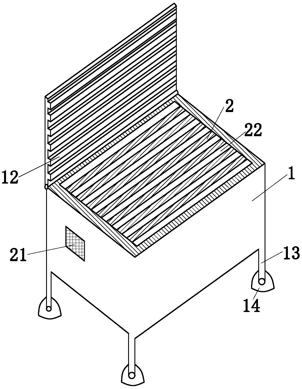
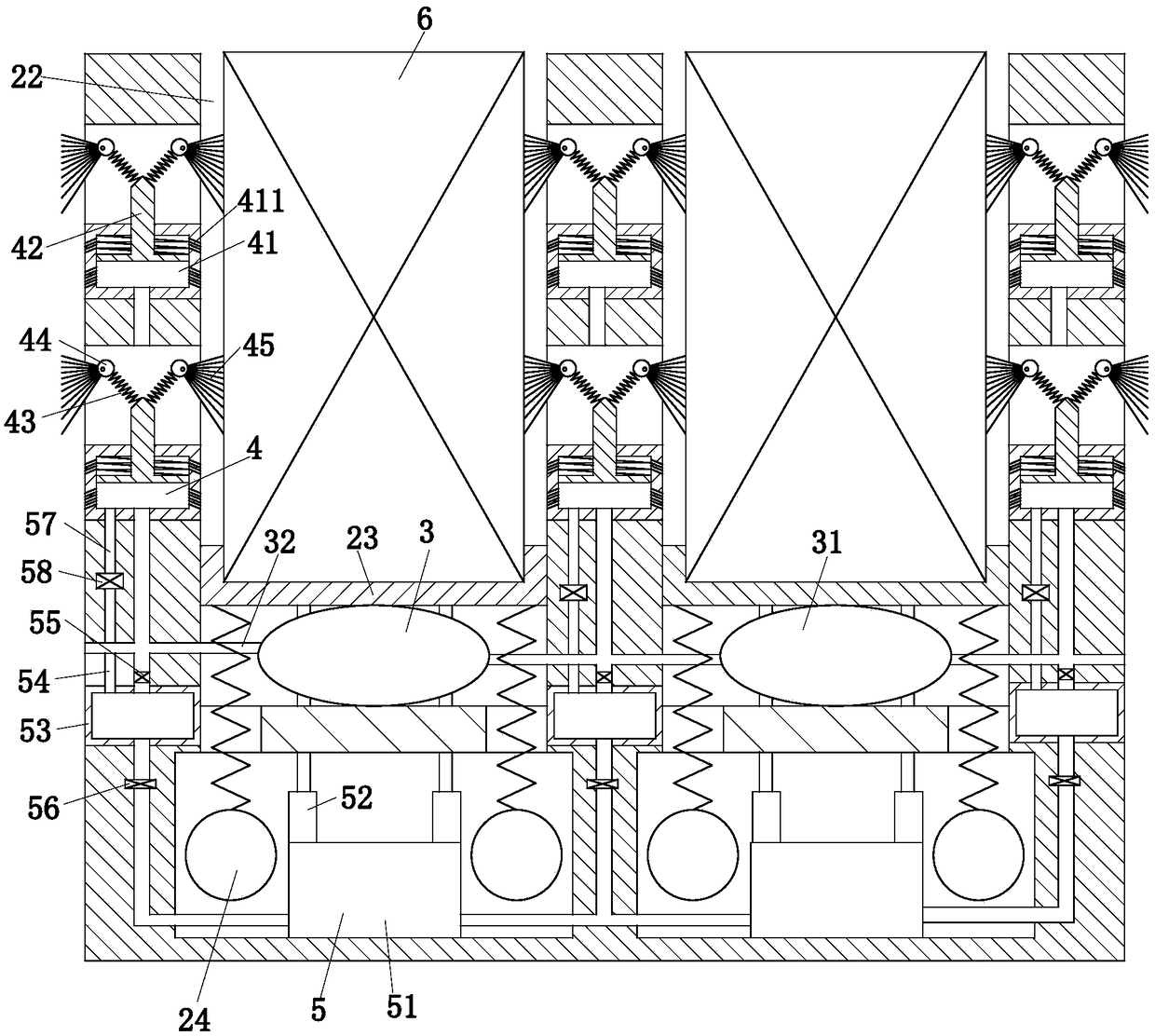
[0023] use Figure 1 to Figure 2 A PCB circuit board transportation device of the present invention is described as follows.

[0024] Such as figure 1 As shown, a PCB circuit board transportation device includes a box body 1, a box cover 12, a box foot 13 and a PCB circuit board placement unit. Adaptation, the box cover 12 is provided with strip ribs, and the strip ribs are used to avoid the direct rigid collision between the PCB circuit board 6 and the box cover 12; the material of the strip ribs is organic silicon material, and the organic silicon material has flexibility; The box feet 13 are located at the four corners of the box body 1, and the box feet 13 are equipped with a Lelo triangular wheel 14 for the walking of the box body 1. The Lailo triangle wheel 14 can improve the up and down vibration amplitude of the PCB circuit board transport device, which is beneficial to the inflation module. 3 fast inflation; the PCB circuit board placement unit is fixed in the box b...


PUM


Abstract

The invention belongs to the technical field of circuit board delivery, and particularly relates to a PCB circuit board delivery device. The device comprises a box body, a box cover, box feet and a PCB circuit board placing unit, the box cover is hinged to the upper end of the box body, the box cover fits the box body, strip-shaped ribs are arranged on the box cover, and the strip-shaped ribs areused for preventing the direct rigid collision of the PCB circuit board and the box cover; the box feet are located at the four corners of the box body, Lello triangular wheels used for the moving ofthe box body are installed on the box feet, the up and down vibration amplitude of the PCB circuit board delivery device can be improved by the Lello triangular wheels to facilitate the rapid inflation of an inflation module; a PCB circuit board placing unit is fixed to the interior of the box body; the PCB circuit board placing unit comprises an installing body, an inflation module, an anti-collision module, a jacking module and a controller. By means of the device, the damage degree of PCB circuit boards in the transportation process can be reduced, and the transportation efficiency of the PCB circuit boards transported by a transportation vehicle can be improved.

Description

technical field [0001] The invention belongs to the technical field of circuit board transportation, in particular to a PCB circuit board transportation device. Background technique [0002] A PCB circuit board is a printed circuit board, also known as a printed circuit board, which is a provider of electrical connections for electronic components. Its design is mainly layout design. The main advantage of using circuit boards is to greatly reduce wiring and assembly errors, improve automation level and production labor rate. PCB circuit board transport box is an essential transport box for transporting PCB circuit boards. It can ensure that the PCB circuit board reduces cracks during transportation, improves the handling speed, and improves work efficiency. However, the current PCB circuit board transportation boxes are generally purely for loading and operation, and do not play a good protective role. Some processed PCB circuit boards are easy to break, scratch, and scrap ...

Claims


Application Information

Patent Timeline
Patent Type & Authority Applications(China)
IPC IPC(8): B65D81/07
CPCB65D81/07
Inventor 李建
Owner 李建
Why Eureka
Eureka Blog
Learn More