
Micro-gripper for measuring clamping force and jaw displacement by optical fiber Fabry-Perot interferometer

An interferometer and clamping force technology, applied in the field of micro clamps, can solve the problems of inability to accurately measure the clamping force and jaw displacement, and achieve the effect of simple structure, small resolution and high sensitivity

Active Publication Date: 2019-01-18
CHONGQING UNIV
View PDF6 Cites 9 Cited by
  • Summary
  • Abstract
  • Description
  • Claims
  • Application Information

AI Technical Summary

Problems solved by technology

[0007] The object of the present invention is to provide a kind of micro gripper that utilizes optical fiber Fabry-Perot interferometer to measure clamping force and gripper displacement, to solve the problem that micro grippers in the prior art cannot accurately measure gripping force and gripper displacement at the same time measurement problem

Method used


Image

  • Micro-gripper for measuring clamping force and jaw displacement by optical fiber Fabry-Perot interferometer
  • Micro-gripper for measuring clamping force and jaw displacement by optical fiber Fabry-Perot interferometer
  • Micro-gripper for measuring clamping force and jaw displacement by optical fiber Fabry-Perot interferometer

Examples


Embodiment Construction

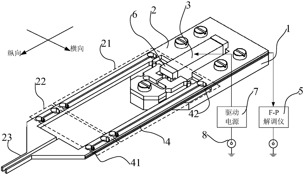
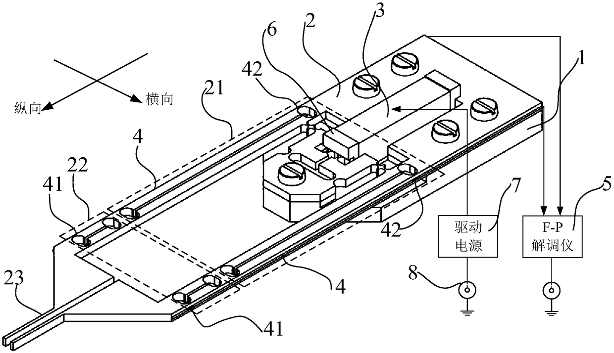
[0049] Reference Figure 1 to Figure 14 , The present invention provides a micro-clamp that uses an optical fiber Fabry-Perot (Fabry-Perot) interferometer to measure the clamping force and the displacement of the clamping jaws, including: a base 1, a single piece fixed on the base 1. The flexible mechanism 2, the actuator 3 installed in the cavity opened on the single-piece flexible mechanism 2, the controller, the FP demodulator 5 connected to the controller, and the optical fiber Fabry-Perot complex connected to the FP demodulator 5 With the sensor 4, the single-piece flexible mechanism 2 includes: a displacement amplifying mechanism 21, two symmetrically arranged clamping force sensing mechanisms 22, and two symmetrically arranged clamping jaws 23, an input stage 211 of the displacement amplifying mechanism 21 and an actuator 3 In abutment, the two output stages 212 of the displacement amplifying mechanism 21, the two clamping force sensing mechanisms 22 and the two clamping ...


PUM


Abstract

The invention relates to a micro-gripper for measuring the clamping force and the jaw displacement by an optical fiber Fabry-Perot interferometer to solve the problem that the micro-gripper in the prior art cannot measure the clamping force and the jaw displacement accurately at the same time. The technical scheme is that the micro-gripper comprises a base, a monolithic flexible mechanism fixed onthe base, an actuator installed in a cavity provided on the monolithic flexible mechanism, a controller, an F-P demodulator connected with the controller, and an optical fiber Fabry-Perot multiplexedsensor connected with the F-P demodulator. The monolithic flexible mechanism comprises: a displacement amplifier mechanism, two clamping force sensing mechanisms symmetrically arranged and two clamping jaws symmetrically arranged, the input stage of the displacement amplifying mechanism is in contact with the actuator, the two output stages of the displacement amplifying mechanism, the two clamping force sensing mechanisms and the two clamping jaws correspond one by one, and the output stage of the displacement amplifying mechanism, the clamping force sensing mechanism and the clamping jaws are sequentially connected.

Description

Technical field [0001] The invention relates to the field of micro-manipulation and micro-assembly, in particular to a micro-clamp that uses an optical fiber Fabry-Perot interferometer to measure clamping force and clamping jaw displacement. Background technique [0002] With the rapid development of Micro-Electro-Mechanical System (MEMS), coupled with the traditional MEMS manufacturing process that cannot produce small parts with complex three-dimensional geometric structures and composed of different materials, micro-assembly and micro-manipulation technologies have emerged A pivotal role. Micro clamps are the end effectors of micro assembly systems and micro operating systems. They are in direct contact with the objects to be operated. They play a decisive role in the completion of micro assembly and micro manipulation tasks. They are widely used in biomedicine, electronics manufacturing, and aerospace. And military and other fields. [0003] Commonly used micro clamp drive me...

Claims


Application Information

Patent Timeline
IPC IPC(8): B81B3/00B81B7/02G01D21/02
CPCB81B3/0027B81B7/02G01D21/02
Inventor 王代华赵建宇
Owner CHONGQING UNIV
Learn More