
High-difficulty waste water evaporator

A waste water evaporator, a difficult technology, applied in the direction of steam generation, steam generation device, water/sewage treatment, etc., can solve the problem of black and odorous water body, can not reduce the concentration of nitrogen and phosphorus in water body, and dissolved oxygen in difficult waste water In order to achieve the effect of overcoming poor governance effects, overcoming low governance efficiency, and improving treatment quality

Pending Publication Date: 2019-01-18
SHENZHEN HDN WATER TREATMENT EQUIP
View PDF16 Cites 0 Cited by
  • Summary
  • Abstract
  • Description
  • Claims
  • Application Information

AI Technical Summary

Problems solved by technology

[0003] In the prior art, two methods are usually used to treat the difficult wastewater. One is the aeration method. The aeration method is to increase the oxygen content in the water body by introducing air or oxygen into the difficult wastewater. When using this method to treat difficult wastewater, a large amount of oxygen-containing gas needs to be introduced, and the scale is huge. At the same time, this method cannot reduce the concentration of nitrogen and phosphorus in the water body, so it cannot fundamentally solve the problem of water body pollution. Black and smelly problem; the other is the method of planting plants, by which the nitrogen and phosphorus in the black and smelly water can be absorbed, but in this method, the oxygen produced by the photosynthesis of the herb is released into the air through the leaves, which is difficult to solve The problem of low dissolved oxygen in difficult wastewater, therefore, the treatment effect is not obvious, the treatment efficiency is low, and the use is limited

Method used


Image

  • High-difficulty waste water evaporator

Examples


Embodiment Construction

[0019] The following will clearly and completely describe the technical solutions in the embodiments of the present invention with reference to the accompanying drawings in the embodiments of the present invention. Obviously, the described embodiments are only some, not all, embodiments of the present invention. Based on the embodiments of the present invention, all other embodiments obtained by persons of ordinary skill in the art without making creative efforts belong to the protection scope of the present invention.

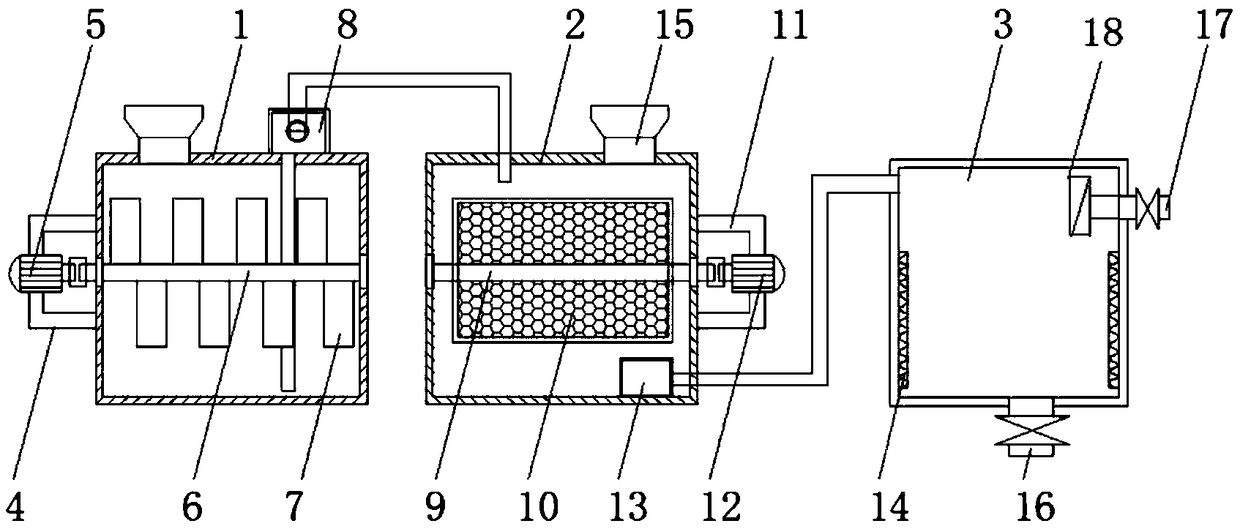
[0020] see figure 1 An embodiment provided by the present invention: an emergency purification treatment equipment for black and odorous water, including a first reaction tank 1, a second reaction tank 2 and an evaporation tank 3; the left side of the first reaction tank 1 passes through the first motor The seat 4 is fixedly equipped with a first motor 5, and a first rotating shaft 6 is provided for rotation in the first reaction tank 1, and the first motor 5 ...


PUM

PropertyMeasurementUnit
particle size (mesh)aaaaaaaaaa

Abstract

The invention discloses a high-difficulty waste water evaporator. The high-difficulty waste water evaporator comprises a first reaction tank, a second reaction tank and an evaporation tank; the left side of the first reaction tank is fixedly provided with a first motor by virtue of a first motor holder, a first rotating shaft is rotatably arranged in the first reaction tank, and the first motor isfixedly connected with the left end of the first rotating shaft by virtue of a coupler; the first rotating shaft is provided with first stirring vanes located in the first reaction tank; the top of the first reaction tank is provided with a lifting pump, a water inlet of the lifting pump contacts the bottom of the first reaction tank by virtue of a pipeline; a water outlet of the lifting pump iscommunicated with a second reaction tank by virtue of a straight pipe; and a second rotating shaft is rotatably arranged inside the second reaction tank. By adopting the high-difficulty waste water evaporator provided in the invention, the high-difficulty waste water is treated by virtue of three steps, so that the purification quality of the high-difficulty waste water can be effectively improved, and the purification efficiency of the high-difficulty waste water can be greatly improved.

Description

technical field [0001] The invention relates to the technical field of vertical machining centers, in particular to a difficult waste water evaporator. Background technique [0002] With the continuous development of industrialization, the discharge of industrial wastewater and domestic water makes the river water suffer from organic pollution and become a eutrophic water body. Microorganisms consume oxygen in this water body and reproduce in large numbers, so that the oxygen in the water body is exhausted, causing the water body to be hypoxic. In the anoxic water body, organic pollutants are anaerobically decomposed to form a large amount of sulfide, which makes the water body black and smelly, and the hydrogen sulfide gas in the black odorous water body causes air pollution. [0003] In the prior art, two methods are usually used to treat the difficult wastewater. One is the aeration method. The aeration method is to increase the oxygen content in the water body by introdu...

Claims


Application Information

Patent Timeline
Patent Type & Authority Applications(China)
IPC IPC(8): C02F9/14F22B33/00
CPCF22B33/00C02F9/00C02F3/342C02F1/04C02F1/46176
Inventor 吴威
Owner SHENZHEN HDN WATER TREATMENT EQUIP
Learn More