
Large-span special-section intersecting truss structure and installation method thereof

A technology of special-shaped section and truss structure, applied in the direction of truss structure, girders, trusses, etc., can solve problems such as differences in angle and elevation, inability to guarantee stability, installation quality influence, etc., to achieve strong structural stability and force transmission. Reasonable and guaranteed effect

Active Publication Date: 2019-01-18
CHINA CONSTR SECOND BUREAU INSTALLATION ENG
View PDF5 Cites 0 Cited by
  • Summary
  • Abstract
  • Description
  • Claims
  • Application Information

AI Technical Summary

Problems solved by technology

Existing special-shaped cross-section truss structures generally have special-shaped cross-sections that are simply connected by tie rods. The structure seems simple, but there are strong force requirements for the support and tie rods. At the same time, there is no longitudinal connection between the vertical rods, so its stability cannot be guaranteed.
The section shapes of the stressed trusses are similar but the sizes are different, and there are differences in angles and elevations. It is difficult to control the shape, position, and force state during installation during high-altitude construction, and it is easy to affect the installation quality. have an impact

Method used


Image

  • Large-span special-section intersecting truss structure and installation method thereof
  • Large-span special-section intersecting truss structure and installation method thereof
  • Large-span special-section intersecting truss structure and installation method thereof

Examples


Embodiment Construction

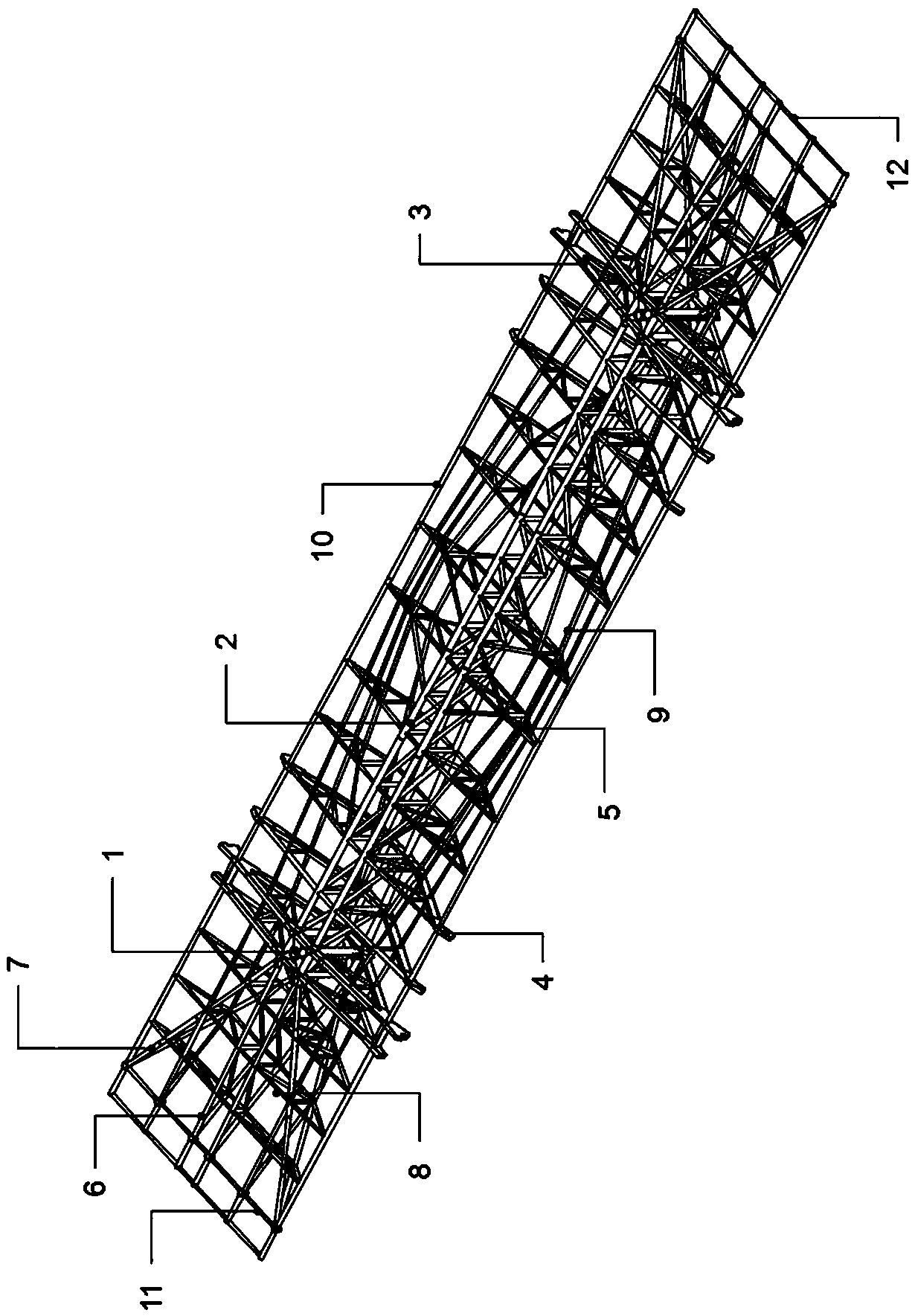
[0041] Hereinafter, embodiments of the large-span special-shaped cross-section cross truss structure and its installation method of the present invention will be described with reference to the accompanying drawings.

[0042] The examples described here are specific specific implementations of the present invention, and are used to illustrate the concept of the present invention. They are all explanatory and exemplary, and should not be construed as limiting the implementation of the present invention and the scope of the present invention. In addition to the embodiments described here, those skilled in the art can also adopt other obvious technical solutions based on the claims of the application and the contents disclosed in the description, and these technical solutions include adopting any obvious changes made to the embodiments described here. Replacement and modified technical solutions. The accompanying drawings in this specification are schematic diagrams, which assist...


PUM


Abstract

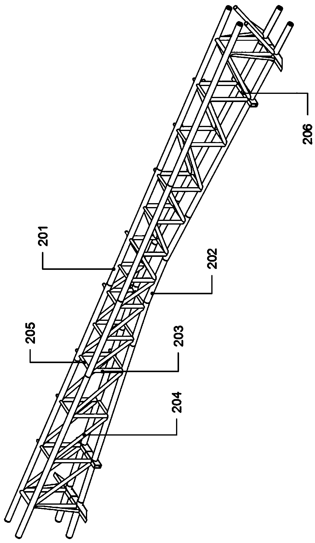
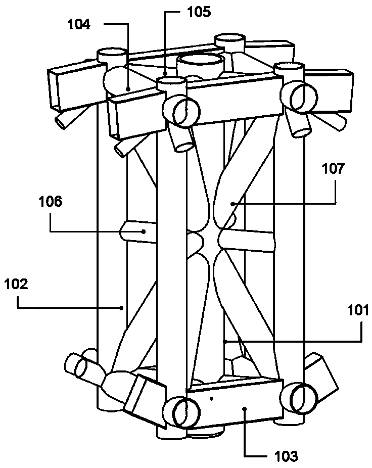
The invention relates to a large-span special-section intersecting truss structure and an installation method thereof. The whole large-span special-section intersecting truss structure is roughly rectangular, and comprises latticed columns, a main stressed truss, wing-modeled main trusses, reinforced-modeled secondary trusses, wing-modeled secondary trusses, cantilever main trusses, oblique combined cantilever main trusses, cantilever-discontinuous secondary trusses and connecting rods arranged among all the trusses. The large-span special-section intersecting truss structure and the installation method have the beneficial effects that a gradient adduction type space structure is adopted, the sizes of single secondary trusses at two sides of the main truss are gradient, the whole secondarytrusses are firstly converged and then widened in a horizontal direction, and are firstly widened and then converged in a longitudinal direction, and the secondary trusses are connected by using theconnecting rods; the stable main stressed system is formed by the latticed columns at two ends and the middle main truss, and then a gradient special-section intersecting truss structure is formed bythe symmetric secondary trusses at two sides; an all-new design idea is provided for a combined form of the latticed columns, the main truss, the secondary trusses and the cantilever truss structures,the structural stability is stronger, the force transfer is more reasonable, the shaping property is stronger, the modeling structure is more reasonable, and the specific image property of the modeling can be better ensured.

Description

technical field [0001] The invention relates to the technical field of large-span special-shaped trusses, in particular to a large-span special-shaped cross-section cross truss structure and an installation method thereof. Background technique [0002] With the continuous development of the domestic economy, overpasses, corridors, and large exhibition halls continue to emerge, and long-span roof trusses of various shapes emerge in endlessly. Existing special-shaped cross-section truss structures generally have special-shaped cross-sections that are simply connected by tie rods. The structure seems simple, but there are strong force requirements for the support and tie rods. At the same time, there is no longitudinal connection between the vertical rods, so its stability cannot be guaranteed. . The section shapes of the stressed trusses are similar but the sizes are different, and there are differences in angles and elevations. It is difficult to control the shape, position,...

Claims


Application Information

Patent Timeline
Patent Type & Authority Applications(China)
IPC IPC(8): E04C3/11E04G21/14
CPCE04C3/11E04G21/14
Inventor 范玉峰张军辉刘方星宗正鑫李国良
Owner CHINA CONSTR SECOND BUREAU INSTALLATION ENG
Learn More